Illuminating device and projector
A technology for lighting devices and optical surfaces, applied to lighting devices, components of lighting devices, projection devices, etc., can solve the problem of increased infrared and ultraviolet rays, reduced filter efficiency, and inability of filters to play their original role, etc. question
- Summary
- Abstract
- Description
- Claims
- Application Information
AI Technical Summary
Problems solved by technology
Method used
Image
Examples
no. 1 Embodiment
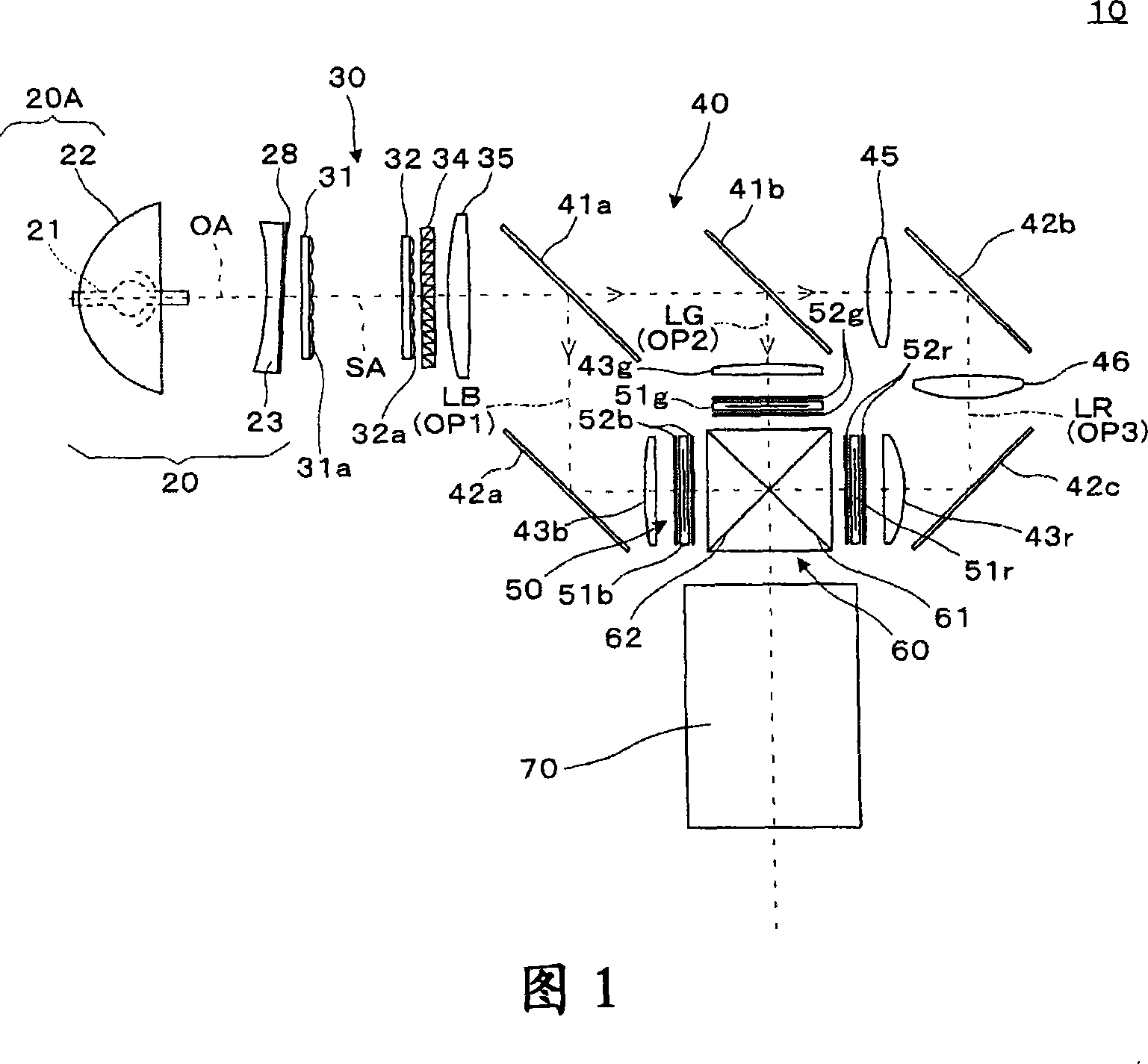
[0030] FIG. 1 is a schematic diagram illustrating the configuration of an optical system of a projector according to a first embodiment of the present invention.
[0031] The projector 10 is an optical device that modulates a light beam emitted from a light source according to image information to form an optical image, and enlarges and projects the optical image on a screen, and is composed of a light source lamp unit 20, an illumination optical system 30, and a color separation device. 40 . The light modulation unit 50 , the cross dichroic prism 60 and the projection optical system 70 . Among them, the light source lamp unit 20 and the illumination optical system 30 constitute an illumination device that emits illumination light for illuminating the light modulator 50 .
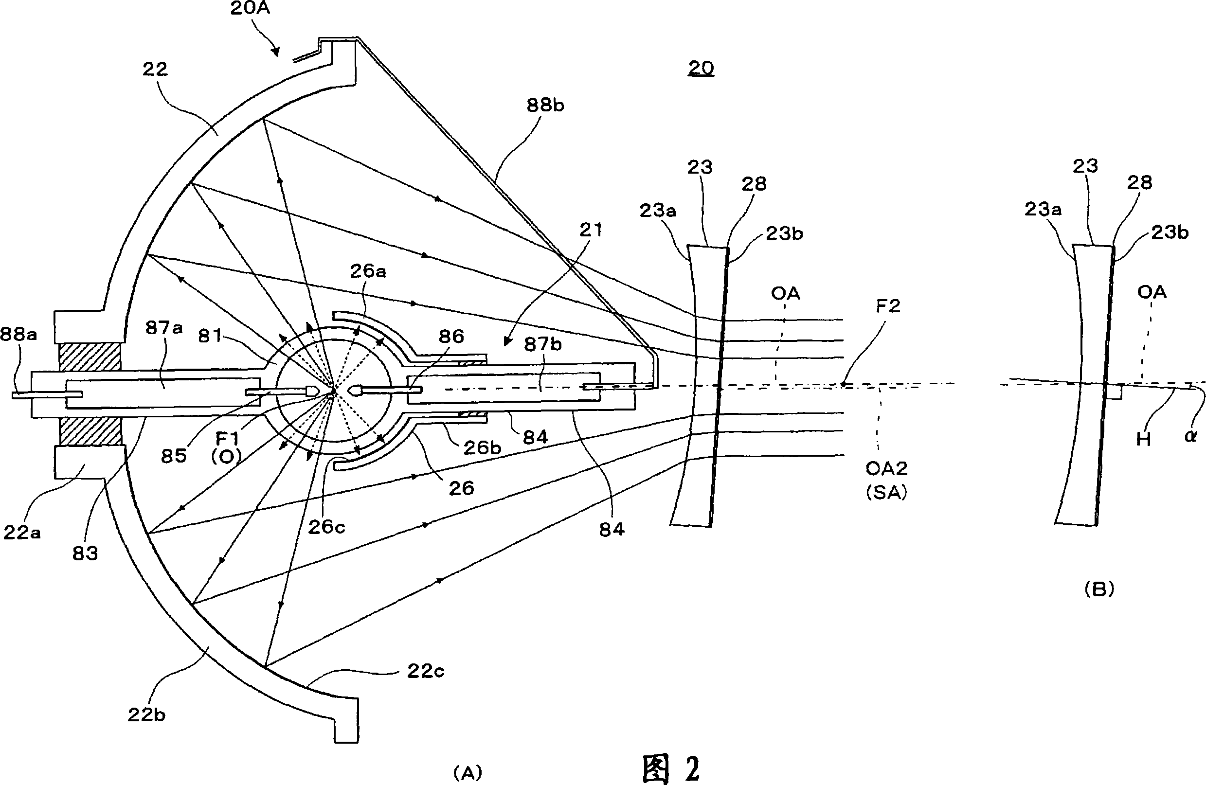
[0032] The light source lamp unit 20 gathers and emits the light beams radiated from the lamp body 21 to the surroundings, and illuminates the light modulator 50 through the illumination optical system 30 a...
no. 2 Embodiment
[0060] Fig. 5 is a side view illustrating the light source lamp unit 120 of the lighting device according to the second embodiment. The light source lamp unit 120 is a component assembled in place of the light source lamp unit 20 in the projector 10 according to the first embodiment shown in FIG. 20 have the same structure, and the common parts are denoted by the same symbols and repeated descriptions are omitted.
[0061] In the light source lamp unit 120 of this embodiment, the main reflector 122 is not an ellipse but a paraboloid. The main reflector 122 reflects light emitted from a lamp body (not shown) to emit as parallel light. Therefore, a plano-convex lens 123A and a concave-plano lens 123B are sequentially arranged on the light-emitting side of the main reflector 122 , that is, the light-emitting side of the lamp device 120A having the main reflector 122 and the lamp body. The plano-convex lens 123A is a lens for changing parallel light emitted from the main mirror ...
no. 3 Embodiment
[0064] In the second embodiment, instead of tilting the plano-convex lens 123A, the concave-plano lens 123B is tilted. On the contrary, it is also possible to form the filter 28 on the flat surface of the plano-convex lens 123A so that the normal line of the flat surface of the plano-convex lens 123A Tilt relative to lamp axis OA. In this embodiment, such an example will be described. Fig. 6 is a side view illustrating the light source lamp unit 220 of the lighting device according to the third embodiment. The light source lamp unit 220 has the same structure as that of the light source lamp unit 120 of the second embodiment except for the parts not described in particular.
[0065] In the light source lamp unit 220 of this embodiment, plano-convex lenses are sequentially disposed on the light emitting side of the main reflector 122, that is, on the light emitting side of the lamp device 120A having the main reflector 122 and the lamp body (not shown). 223A and concave flat ...
PUM
 Abstract
Description
Claims
Application Information
 - R&D
- Intellectual Property
- Life Sciences
- Materials
- Tech Scout
- Unparalleled Data Quality
- Higher Quality Content
- 60% Fewer Hallucinations
Browse by: Latest US Patents, China's latest patents, Technical Efficacy Thesaurus, Application Domain, Technology Topic, Popular Technical Reports.
© 2025 PatSnap. All rights reserved.Legal|Privacy policy|Modern Slavery Act Transparency Statement|Sitemap|About US| Contact US: help@patsnap.com


