
Full digital sliding pulse signal generator

A technology of pulse signal and slip, applied in the field of signal source, can solve the problems of narrow parameter range, inconvenient use, low precision, etc.

Inactive Publication Date: 2007-10-03
CHENGDU UNIVERSITY OF TECHNOLOGY
View PDF0 Cites 14 Cited by
  • Summary
  • Abstract
  • Description
  • Claims
  • Application Information

AI Technical Summary

Problems solved by technology

[0003] In view of the fact that such products have not yet appeared on the market, some of them are only at the early stage of technology, mainly composed of discrete components, with low precision, narrow parameter range, and inconvenient use, which can no longer meet the requirements of current applications. need

Method used


Image

  • Full digital sliding pulse signal generator
  • Full digital sliding pulse signal generator
  • Full digital sliding pulse signal generator

Examples


Embodiment Construction

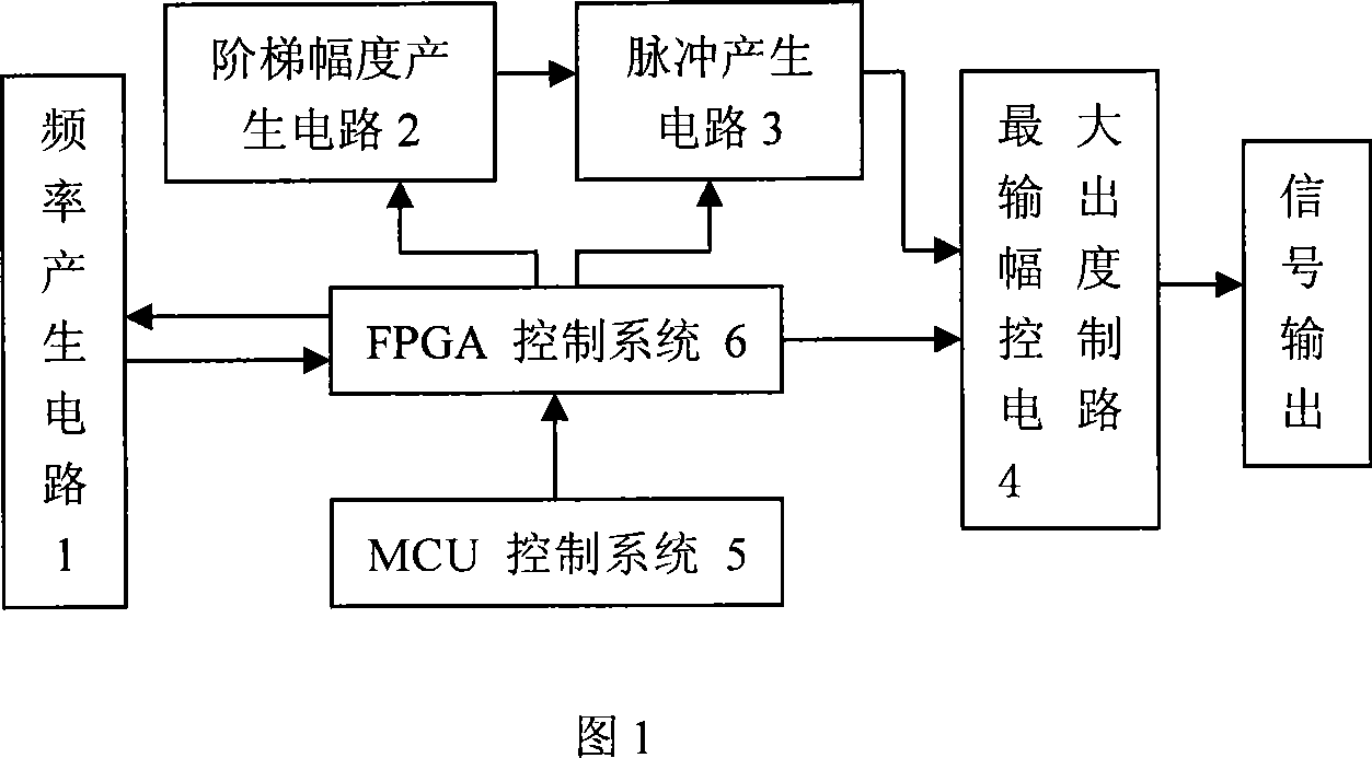
[0022] 1. The whole instrument adopts the joint control mechanism of FPGA control system 6 and MCU control system 5, realizes the intelligent setting of various parameters of the sliding instrument through the MCU control system 5, and completes the transmission with the FPGA control system 6 through the communication protocol , and control the operation of the entire system, the FPGA control system 6 uses its high-speed parallel features to complete the specific realization of each functional module in the system, which reduces the workload of the MCU and ensures the accuracy of the instrument. As shown in Figure 6.

[0023] 2. Frequency generating circuit 1

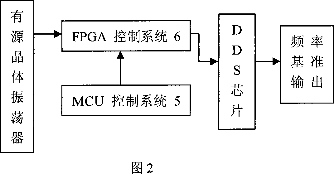
[0024] The schematic block diagram of the frequency generation circuit is shown in Figure 2. The active crystal oscillator generates a 20MHz clock signal, which is sent to the FPGA control system 6, and the frequency is multiplied to 100MHz by its internal phase-locked loop (PLL) module. Simultaneously, the FPGA contro...


PUM


Abstract

A slip pulse signal generator of digital type is prepared as using pulse frequency generating circuit to provide clock reference for whole system, using MCU control unit to set all parameters for whole system, using EPGA control unit to control step amplitude generating circuit based on reference of said clock, using internal time sequence module of FPGA control unit to generate control signal for controlling pulse generating circuit to generate pulse signal and realizing design of maximum pulse amplitude control circuit by FPGA control unit in order to achieve purpose of controlling slip signal maximum amplitude.

Description

technical field [0001] The invention is a special signal source for an amplitude / frequency spectrum (such as nuclear energy spectrum) analysis instrument, which can output a narrow pulse sequence with variable maximum pulse amplitude, variable frequency and variable pulse width. It is specially used to calibrate the main technical indicators such as differential linearity, integral linearity and channel drift of multi-channel pulse amplitude analyzers, and can also test the threshold linearity, channel width and threshold drift of single-channel pulse amplitude analyzers. In addition, this instrument can also be used as a standard frequency pulse generator. Background technique [0002] According to the needs of practical application, the invention is mainly developed and designed for the energy spectrum measuring instrument in nuclear technology. The generated slip signal can detect the nuclear energy spectrometer to check its performance. [0003] In view of the fact tha...

Claims


Application Information

Patent Timeline
Patent Type & Authority Applications(China)
IPC IPC(8): H03K4/02H03K5/22
Inventor 庹先国李向阳王洪辉穆克亮
Owner CHENGDU UNIVERSITY OF TECHNOLOGY
Learn More