Method and device for scanning optical fault image

A technology of image scanning and optical tomography, used in measurement devices, material analysis and diagnosis through optical means, etc., can solve the problem of poor resolution, decreased signal-to-noise ratio of interference signals, and inability to accurately know the change of refractive index of medium 11, etc. problem, to achieve the effect of reducing the scattering effect and the difficulty of erection

Inactive Publication Date: 2010-12-29
周晟
View PDF5 Cites 1 Cited by
  • Summary
  • Abstract
  • Description
  • Claims
  • Application Information

AI Technical Summary

Problems solved by technology

However, because the change of the refractive index of the medium 11 cannot be known exactly, the approximate refractive index can only be used as the refractive index of the compensator
[0016] Whether it is due to the use of the focusing lens 15 with a high numerical aperture, or the aberration and dispersion difference (dispersion) caused by the signal beam 101 entering the medium 11 deeper, it will cause the optical path of the signal beam 101 and the reference beam 102 Asymmetry, which widens the wave packet of the interference signal, resulting in poor resolution
[0017] Furthermore, because the medium 11 can scatter the signal beam 101, especially when the medium 11 is a high scattering object, the reflected light from other depth positions in the medium 11 can also pass through the pinhole, resulting in a signal-to-noise ratio (SNR) of the interference signal. ) decreases, thus reducing the quality of the tomographic image

Method used


Image

  • Method and device for scanning optical fault image
  • Method and device for scanning optical fault image
  • Method and device for scanning optical fault image

Examples


Embodiment Construction

[0043] The aforementioned and other technical contents, features and effects of the present invention will be clearly presented in the following detailed description of four embodiments with reference to the accompanying drawings.

[0044] For convenience of description, in the following embodiments, the same elements are denoted by the same reference numerals.

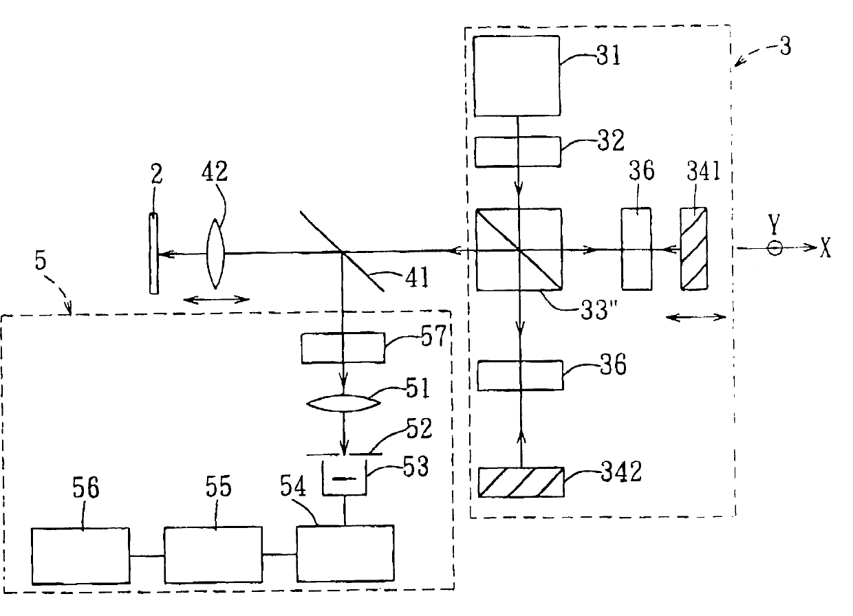
[0045] refer to Figure 4 , the first preferred embodiment of the optical tomography scanning method and device thereof of the present invention includes a dual-frequency beam generating unit 3 , a relay beam splitter 41 , a focusing lens 42 and a signal processing unit 5 .

[0046] The dual-frequency beam generating unit 3 includes a low-coherence light source 31 such as a super-brightness diode (SLD), through a polarizer (polarizer) 32 that can adjust the polarization angle to generate a 45° linearly polarized beam, by a polarizer The polarizing beam splitter (Polarizing Beam Splitter, PBS) 33'' divides the linearl...


PUM


Abstract

An optical laminagraphic image-scanning method for testing a medium includes such steps as providing the low-homology light beams with frequency associated photon pair, focusing said light beams at different positions with different depths in the medium, reflecting by said medium to obtain the lift beam of signal, and analyzing the signal by a signal processing unit to obtain the laminagraphic image of said medium. Its apparatus is also disclosed.

Description

【Technical field】 [0001] The present invention relates to a tomography scanning device and its method, in particular to an optical tomography scanning method and its device. 【Background technique】 [0002] Optical Coherence Tomography (OCT) is a very useful tomographic scanning device currently used in ophthalmology, dermatology, cardiovascular and other related medical diagnoses, because it can provide clear tomographic images required for diagnosis of various diseases (sectional image), and compared with other non-invasive medical imaging techniques, such as computer tomography (Computer Tomography, CT), magnetic resonance imaging (Magnetic Resonance Imaging, MRI) and ultrasound (ultrasound), OCT can provide better spatial resolution. [0003] Basically, OCT is a Maxson interferometer using a low coherence light source. The Maxson interferometer interferes only when the optical path difference between the signal beam and the reference beam is smaller than the coherence l...

Claims


Application Information

Patent Timeline
Patent Type & Authority Patents(China)
IPC IPC(8): A61B5/00G01N21/84
Inventor 周晟郭文娟
Owner 周晟
Why Eureka
Try Eureka