Composite heat insulation plate

A technology of composite thermal insulation and thermal insulation layer, which is applied in the direction of thermal insulation, floors, building components, etc. It can solve the problems of complex construction process, poor durability and fireproof performance, and poor bonding ability of the base wall of the external thermal insulation system. Achieve the effects of shortening the construction period, fast installation speed and easy operation

Inactive Publication Date: 2007-10-10
戴长虹
View PDF0 Cites 27 Cited by
  • Summary
  • Abstract
  • Description
  • Claims
  • Application Information

AI Technical Summary

Problems solved by technology

[0003] The purpose of the present invention is to provide a composite thermal insulation board to replace the existing lightweight thermal insulation materials such as polystyrene board and polyurethane foam board to solve the problem of low strength of materials such as polystyrene board and polyurethane foam board and the ability to bond with the base wall. Poor, poor durability and fire performance, and the construction process of the external thermal insulation system is complicated, the cycle is long, and problems such as drums and cracks are prone to occur after completion

Method used


Image

  • Composite heat insulation plate
  • Composite heat insulation plate
  • Composite heat insulation plate

Examples


Embodiment 1

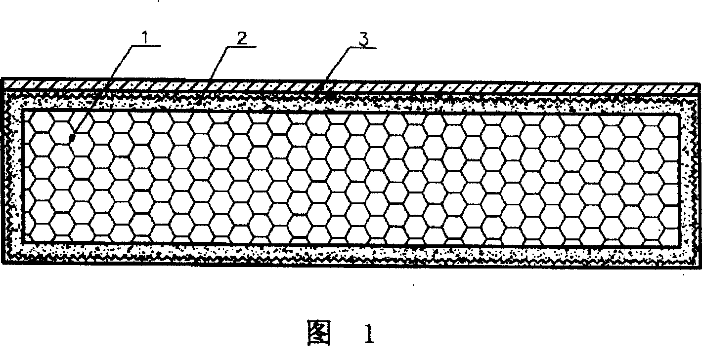
[0012] Embodiment 1: As shown in Figure 1, the composite thermal insulation board of the present invention is composed of a thermal insulation layer 1, a reinforced protective layer 2 and a finishing layer 3. Insulation layer 1 is expanded polystyrene board (EPS); reinforced protective layer 2 is composed of non-cement-based polymer mortar and a layer of glass fiber mesh cloth; facing layer 3 is putty on the upper surface of reinforced protective layer 2 , Spray or brush paint.

Embodiment 2

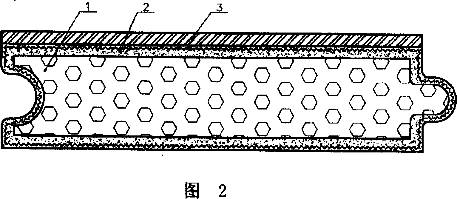
[0013] Embodiment 2: As shown in Figure 2, the composite thermal insulation board of the present invention is composed of a thermal insulation layer 1, a reinforced protective layer 2 and a finishing layer 3. Insulation layer 1 is extruded polystyrene board (XPS); reinforced protective layer 2 is polymer cement mortar, and there is a layer of galvanized steel wire mesh inside the reinforced protective layer 2; the decorative layer 3 is a ceramic tile pasted on the reinforced protective layer 2 .

Embodiment 3

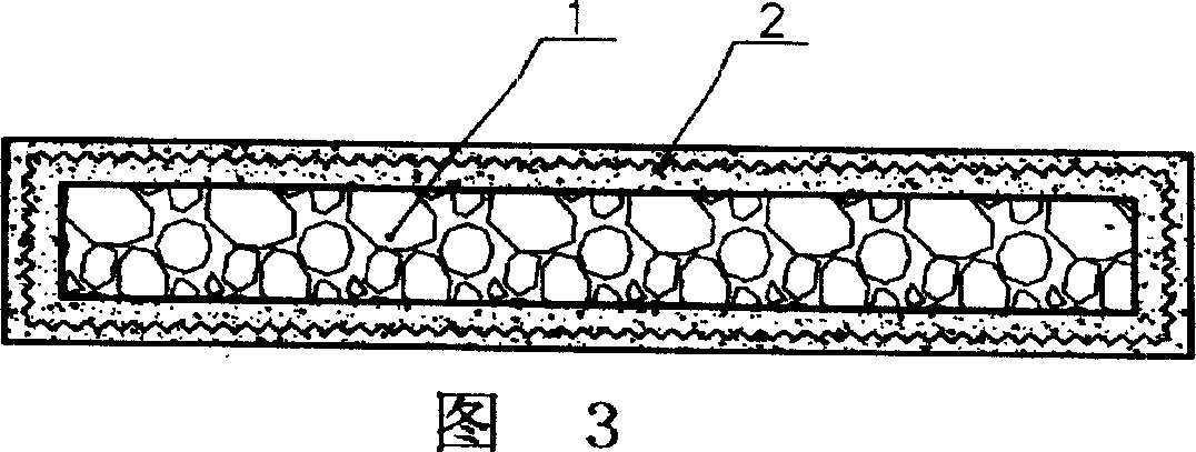
[0014] Embodiment 3: As shown in Figure 3, the composite thermal insulation board of the present invention consists of a thermal insulation layer 1 and a reinforced protective layer 2. The insulation layer 1 is an expanded polystyrene board; the reinforced protective layer 2 is composed of polymer cement mortar and a layer of alkali-resistant glass fiber mesh cloth, and the reinforced protective layer 2 covers the entire outer surface of the insulation layer 1. As shown in Figure 4, stack two composite thermal insulation boards with the same length and width in Figure 3, and move them along the diagonal line of the upper surface, stagger them for a certain distance, and then bond them together. For lap connection, electricity can be used as a place to install anchor bolts or expansion bolts. As shown in Figure 5, the finishing layer 3 is made by scraping putty, spraying or brushing paint on the upper surface of the composite thermal insulation board shown in Figure 4, and finally ...


PUM


Abstract

The present invention relates to a composite heat-insulating plate. It is mainly formed from heat-insulating layer and reinforced protection layer. It is mainly characterized by that said reinforced protection layer is set on the outer side of heat-insulating layer. Said reinforced protection layer can at least cover upper and lower two surfaces and left and right two side surfaces of said heat-insulating layer, said reinforced protection layer and heat-insulating layer are connected into one body, and on the reinforced protection layer a finishing coat can be made up.

Description

Technical field [0001] The invention relates to a composite thermal insulation board, which belongs to the technical field of building thermal insulation materials. Background technique [0002] The existing thermal insulation system has many forms, the more commonly used ones are rubber powder polystyrene particle thermal insulation system, polystyrene board (EPS and XPS) thermal insulation system and polyurethane foam thermal insulation system. The rubber powder polystyrene particle insulation system has the advantages of simple construction, low cost, good fire resistance, no hollowing, no falling off, etc., but the insulation performance is not as good as the same thickness of polystyrene board and polyurethane foam board. The insulation performance of the polystyrene board insulation system is better than that of the rubber powder polystyrene particles, but due to its low strength, poor durability and poor adhesion to the foundation wall, problems such as bulging, falling of...

Claims


Application Information

Patent Timeline
Patent Type & Authority Applications(China)
IPC IPC(8): E04B1/80E04F13/075E04F15/00
Inventor 戴长虹
Owner 戴长虹
Why Eureka
Try Eureka