Semi solid metal apparent viscosity detector

A semi-solid metal, apparent viscosity technology, applied in measuring devices, flow characteristics, instruments, etc., can solve the problems of easily damaged torque sensors, drastic changes in the temperature field in the furnace, large torque impact values, etc., to prevent alloy oxidation. , Improve the thermal conductivity, the effect of small temperature disturbance

Inactive Publication Date: 2007-10-10
TAIYUAN UNIVERSITY OF SCIENCE AND TECHNOLOGY
View PDF0 Cites 16 Cited by
  • Summary
  • Abstract
  • Description
  • Claims
  • Application Information

AI Technical Summary

Problems solved by technology

In 1991, Flemings et al. prepared Sn-Pb alloy semi-solid slurry with a stirring device consisting of a set of graphite-made concentric belt-toothed inner and outer cylinders. Later, H.Lehuy et al. prepared Al-Cu, Ai-Zn, Al-Si alloy semi-solid slurry, and some people have prepared ZA-22 alloy semi-solid slurry by using a spiral agitator. Su Huaqin of Southeast University in China developed AZ91D magnesium alloy ingot under the protection of argon on the blade stirring device. At the same time These experts all reflect the apparent viscosity by measuring the torque, but these methods and equipment have the following shortcomings in the apparent viscosity measurement and conversion, and the measurement effect is not good: ①The semi-solid metal slurry is too violently stirred and presents a turbulent flow state, the measured torque cannot be converted into a viscosity value through calculation; ② metal stirring paddles and blades are easy to pollute the alloy slurry, and the solid phase fraction that can be processed is limited due to too much resistance; ③ measures to prevent the oxidation of the alloy slurry are lacking, Or due to the tight protection, it is impossible to quickly obtain the sample for analysis; ④ The way of introducing the protective gas is not appropriate, the protection effect is not ideal, or the temperature field in the furnace changes sharply; ⑤ At the moment of starting to stir, the torque has a large impact value, Torque sensors are easily damaged

Method used


Image

  • Semi solid metal apparent viscosity detector
  • Semi solid metal apparent viscosity detector
  • Semi solid metal apparent viscosity detector

Examples


example 1

[0014] Example 1. Measurement of AlSi 4 Mg 2 Apparent Viscosity of Aluminum Alloy Semi-solid Paste

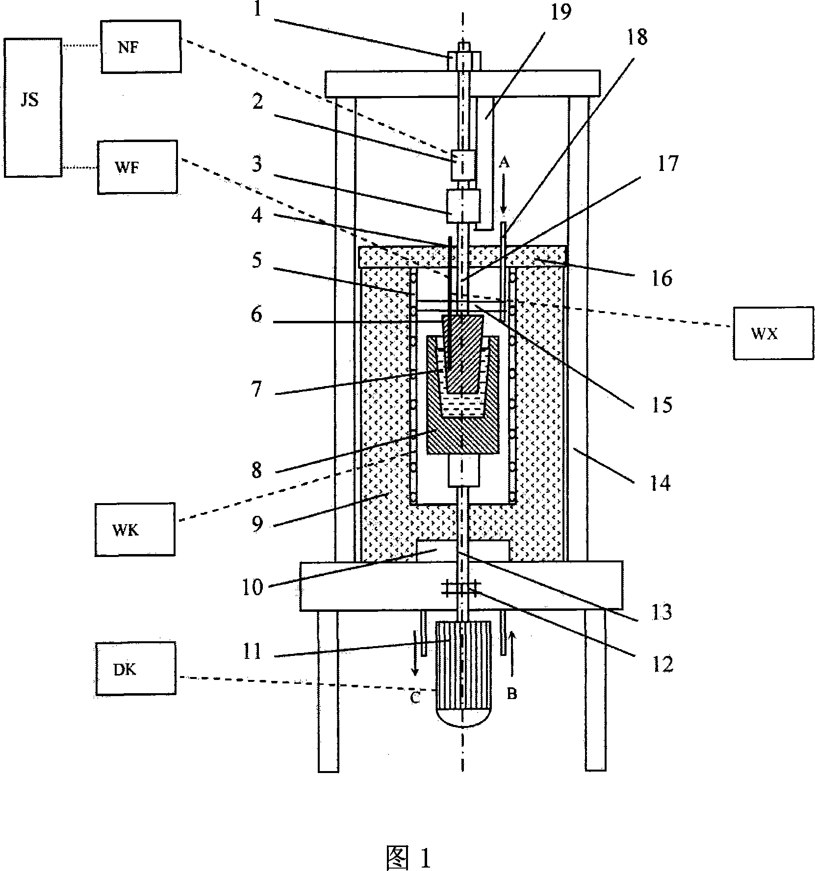
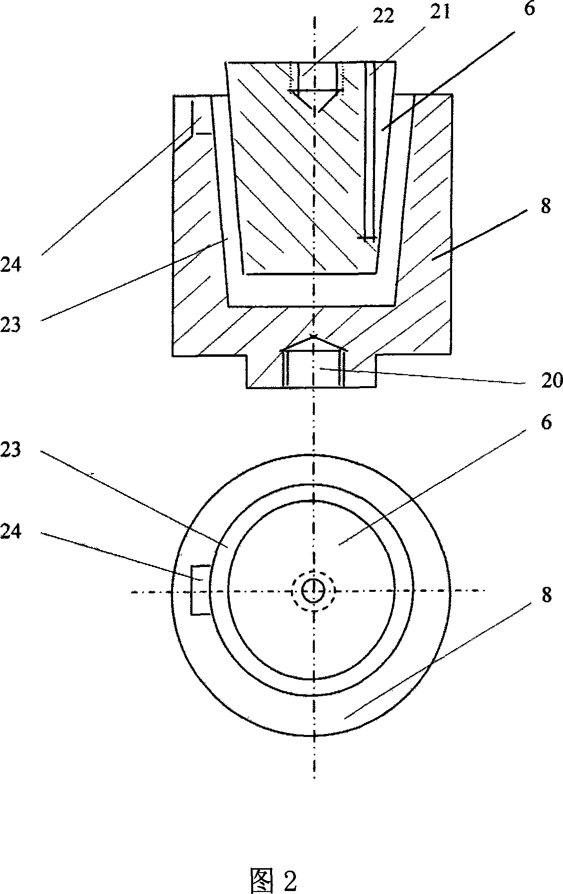
[0015] As shown in Figure 1, the resistance furnace 9 is installed on the frame 14, and a crucible 8 made of graphite is installed in the resistance furnace 9 cavity. The rotating shaft 13 of the crucible 8 is connected with threads, and the lower end of the rotating shaft 13 is connected with the output shaft of the high-frequency speed-regulating motor 11 through a coupling 12. The high-frequency speed-regulating motor 11 is placed at the lower part of the resistance furnace 9 and fixed on the base In the center of the crucible 8 cavity, there is an approximately cylindrical graphite head 6 installed in the air. An annular cavity for filling metal raw materials is formed between the inner wall of the crucible 8 and the graphite head 6. The graphite head 6 and the crucible 8 are coaxial. The center of the upper end of the graphite head 6 is threaded with a threaded hole 22 a...

example 2

[0027] Example 2. Measuring the apparent viscosity of AZ91D magnesium alloy semi-solid slurry

[0028] According to the implementation steps of Example 1, for the AZ91D magnesium alloy, during the solidification process with a cooling rate of 4°C / min, respectively at a shear rate of γ=46.8s -1 , 93.6s -1 , 187.2s -1 and 280.8s -1 Continuous shear was performed to measure the apparent viscosity at different temperatures (ie, different solid phase fractions), and a metallographic sample of the semi-solid slurry was obtained, as shown in FIG. 7 .


PUM


Abstract

A measurement device of apparent viscosity on semisolid metal is prepared for setting a heating furnace on body-frame, erecting rotatable graphite crucible in heating furnace and arranging graphite head on the same shaft with crucible in crucible cavity, setting fixed shaft connected with graphite head through thread on body-frame, setting torque transducer and spacing ledge on fixed shaft, arranging protection gas vent unit at top of heating furnace cavity and using data collection card on computer host board to record torque voltage signal.

Description

Technical field: [0001] The invention belongs to the technical field of metallurgical measurement, in particular to a semi-solid metal apparent viscosity measuring device. Background technique: [0002] In order to provide semi-solid metal apparent viscosity data for semi-solid metal forming equipment, relevant experts at home and abroad have done some preliminary work on the design of apparent viscosity measuring devices. In 1991, Flemings et al. prepared Sn-Pb alloy semi-solid slurry with a stirring device consisting of a set of graphite-made concentric belt-toothed inner and outer cylinders. Later, H.Lehuy et al. prepared Al-Cu, Ai-Zn, Al-Si alloy semi-solid slurry, and some people have prepared ZA-22 alloy semi-solid slurry by using a spiral agitator. Su Huaqin of Southeast University in China developed AZ91D magnesium alloy ingot under the protection of argon on the blade stirring device. At the same time These experts all reflect the apparent viscosity by measuring th...

Claims


Application Information

Patent Timeline
Patent Type & Authority Applications(China)
IPC IPC(8): G01N11/14
Inventor 闫时建闫志杰宫长伟张敏刚
Owner TAIYUAN UNIVERSITY OF SCIENCE AND TECHNOLOGY
Why Eureka
Try Eureka