

High efficiency heat radiation cool plate for electronic device
A heat dissipation cold plate and electronic device technology, applied in the direction of electric solid devices, electrical components, semiconductor devices, etc., can solve the problems that affect the application of high-power electronic devices, low heat transfer efficiency of a single root, small effective heat transfer area, etc., to achieve Compact structure, reliable performance and long service life
- Summary
- Abstract
- Description
- Claims
- Application Information
AI Technical Summary
Problems solved by technology
Method used
Image

Examples
Embodiment 1
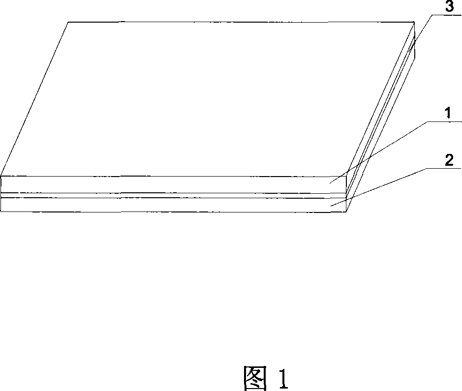
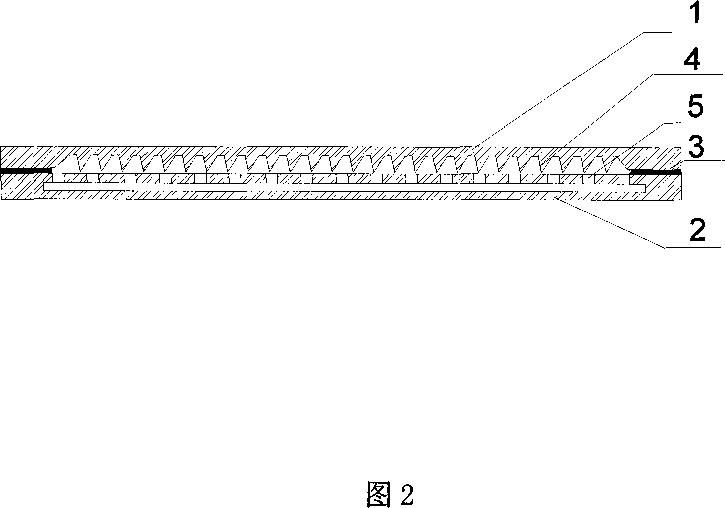
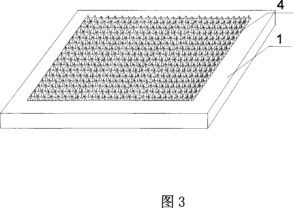
[0021] As shown in Figures 1 and 2, the high-efficiency heat dissipation cold plate for electronic devices has a length, width, and thickness of 80mm, 80mm, and 8mm, respectively, and is formed by bonding and welding the condensation plate 1 and the evaporation plate 2. The condensing plate 1 is formed on the surface of a smooth red copper substrate with a thickness of 3mm, and fine and dense three-dimensional sawtooth fins 4 are formed by a mechanical processing method of plow cutting and extrusion. The evaporation plate 2 is formed on the surface of a smooth red copper substrate with a thickness of 3mm, and a porous surface structure 5 with a bottom interconnected by capillary channels is formed by a mechanical processing method of plow cutting and extrusion. The evaporation surface of the high-efficiency heat dissipation cold plate is closely attached to the chip of the electronic device, and the condensation surface is closely attached to the forced convection electronic ra...
Embodiment 2
[0023] As shown in Figure 1 and Figure 2, the high-efficiency heat dissipation cold plate for electronic devices has a length, width and thickness of 60mm, 60mm and 7mm respectively, and is formed by bonding and welding the condensation plate 1 and the evaporation plate 2. The condensing plate 1 is formed on the surface of a smooth red copper substrate with a thickness of 2.5 cm to form fine and dense three-dimensional sawtooth fins 4 by a mechanical processing method of plow cutting and extrusion. The evaporation plate 2 is formed on the surface of a smooth red copper substrate with a thickness of 2.5mm, and a porous surface structure 5 with a bottom interconnected by capillary channels is formed by a mechanical processing method of plow cutting and extrusion. The evaporation surface of the high-efficiency heat dissipation cold plate is closely attached to the chip of the electronic device, and the condensation surface of the high-efficiency heat dissipation cold plate is clos...
Embodiment 3
[0025] As shown in Figures 1 and 2, the high-efficiency cooling plate for electronic devices has a length, width, and thickness of 50mm, 50mm, and 6mm, respectively, and is formed by bonding and welding the condensation plate 1 and the evaporation plate 2. The condensing plate 1 is formed on the surface of a smooth red copper substrate with a thickness of 2 cm, and fine and dense three-dimensional sawtooth fins 4 are formed by a mechanical processing method of plow cutting and extrusion. The evaporation plate 2 is formed on the surface of a smooth red copper substrate with a thickness of 2mm, and a porous surface structure 5 with a bottom interconnected by capillary channels is formed by a mechanical processing method of plow cutting and extrusion. The evaporation surface of the high-efficiency heat dissipation cold plate is closely attached to the chip of the electronic device, and the condensation surface is closely attached to the forced convection electronic radiator. The ...
PUM
 Abstract
Description
Claims
Application Information