
Dynamotor rotor voltage and current measuring method and its device

A technology for generator rotors and measuring devices, which is applied to measuring devices, measuring current/voltage, and measuring electrical variables, etc., can solve the problems of inability to measure accurately in transient processes, being susceptible to electromagnetic interference, and reducing measurement accuracy, etc., to achieve Excellent anti-electromagnetic interference performance, excellent anti-electromagnetic interference characteristics, and high measurement accuracy

Inactive Publication Date: 2007-10-17
王鹏 +1
View PDF0 Cites 19 Cited by
  • Summary
  • Abstract
  • Description
  • Claims
  • Application Information

AI Technical Summary

Problems solved by technology

Due to the high voltage on the rotor, if a very long metal cable is used to transmit the signal to the measuring device, there will be a great hidden danger in terms of safety. Once the cable fails (grounding or short circuit), it will bring serious consequences. ; In the measurement of the rotor current of the generator, since the output signal of the shunt used for rotor current measurement is generally weak (millivolt level), it is easily affected by electromagnetic interference during long-distance cable transmission, resulting in measurement accuracy decline
Due to the effect of the measurement loop inductance, this measurement method cannot accurately measure some transient processes
At present, there is no transmitter with good transient performance and high accuracy specially used for generator rotor voltage and current measurement on the market.

Method used


Image

  • Dynamotor rotor voltage and current measuring method and its device
  • Dynamotor rotor voltage and current measuring method and its device
  • Dynamotor rotor voltage and current measuring method and its device

Examples


Embodiment Construction

[0028] The method for measuring generator rotor voltage and current proposed by the present invention first collects the voltage signal and current signal of the generator rotor; converts the collected voltage signal and current signal into optical signals respectively; transmits and receives the above-mentioned optical signals over a long distance, and The received optical signal is converted into an electrical signal and output.

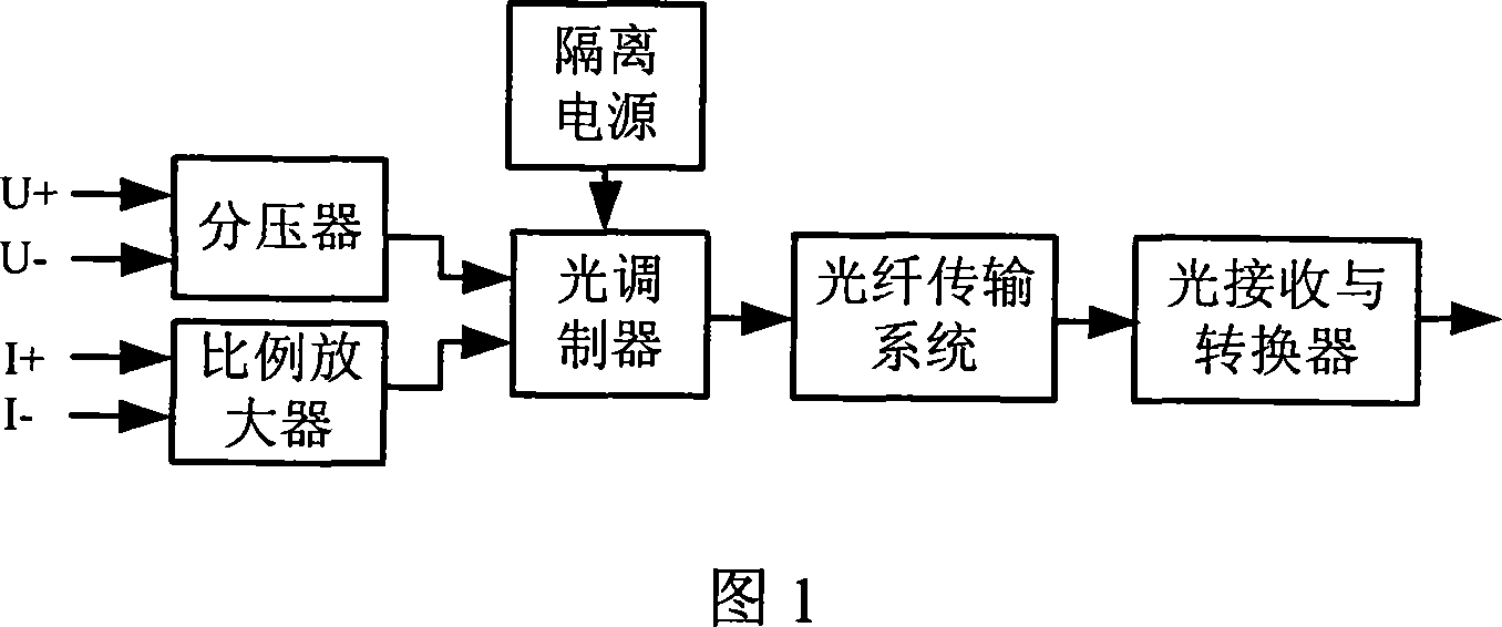
[0029] The structural block diagram of the generator rotor voltage and current measuring device proposed by the present invention is as shown in Figure 1, including

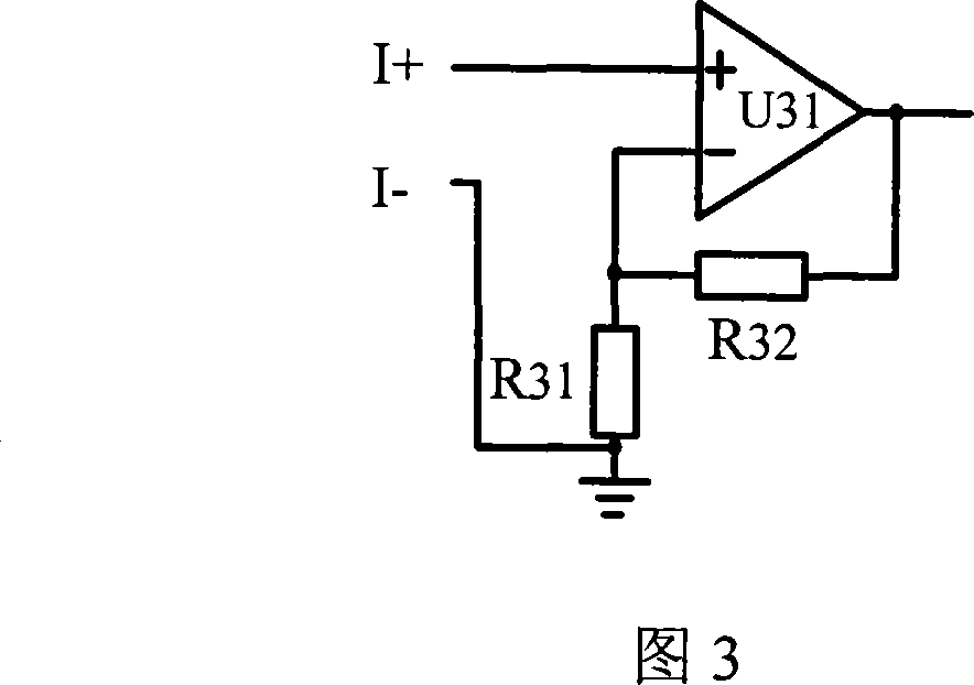
[0030] A voltage divider and a proportional amplifier are respectively used to collect the voltage signal and current signal of the generator rotor, and the voltage divider and the proportional amplifier are respectively connected to the optical modulator;

[0031] The optical modulator is used to convert the voltage signal and the current signal into optical signals respectively;

...


PUM


Abstract

The invention relates to a method and apparatus for measuring voltage and current of generator rotor, which belongs to generator excitation parameter measuring technical field, including: collecting firstly voltage signal and current signal of generator rotor; converting the collected signal into optical signal; transmitting for long distance and receiving the optical signal, and outputting the electrical signal after conversion. The apparatus includes a voltage divider, a proportional amplifier, and an optical modulator of generator rotor side, an optical fiber transmission system, an optical receiving converter and an isolation power source of lower voltage side. The rotor voltage is scaled down by the voltage divider, and the voltage signal for reflecting rotor current variation information outputted by current divider is amplified by the proportional amplifier, then modulated to be optical pulse signal by the optical modulator and transmitted to the optical receiving converter by the optical fiber transmission system, demodulating the optical signal and finally outputting measurement signal of rotor voltage and current. The invention is superior in accurate measurement result, reliability, and excellent temperature stability and anti-vibration characteristics.

Description

technical field [0001] The invention relates to a generator rotor voltage and current measurement method and a device thereof, belonging to the technical field of generator excitation parameter measurement. Background technique [0002] Generator rotor voltage and current signals are the key parameters to monitor the generator excitation parameters. Since the monitoring equipment is far away from the generator, metal cables are generally used to transmit the voltage and current signals of the generator rotor. Due to the high voltage on the rotor, if a very long metal cable is used to transmit the signal to the measuring device, there will be a great hidden danger in terms of safety. Once the cable fails (grounding or short circuit), it will bring serious consequences. ; In the measurement of the rotor current of the generator, since the output signal of the shunt used for rotor current measurement is generally weak (millivolt level), it is easily affected by electromagnetic...

Claims


Application Information

Patent Timeline
IPC IPC(8): G01R19/00
Inventor 王鹏贺丽英
Owner 王鹏
Learn More