Liquid holding bath side-placed smoke gas desulfurization unit

A desulfurization device, side-mounted technology, applied in the separation of dispersed particles, chemical instruments and methods, separation methods, etc., can solve the problems of large transportation power of absorbing liquid, difficult sealing, high reagent cost, etc., saving equipment investment and improving Residence time, the effect of improving utilization

Active Publication Date: 2007-10-31
CHINA PETROLEUM & CHEM CORP +1
View PDF4 Cites 14 Cited by
  • Summary
  • Abstract
  • Description
  • Claims
  • Application Information

AI Technical Summary

Problems solved by technology

[0003] The gas-liquid contact flue gas desulfurization section and the liquid holding tank are built into an integral absorption tower, which has the following disadvantages: (1) limited by the cross-sectional area of ​​the flue gas desulfurization section, the liquid holding tank cross-sectional area cannot be too large. Therefore, in order to ensure that the gas-liquid Good contact and large liquid holding tank volume, the absorption tower is very high, which makes the absorption tower cost higher per unit volume, and the absorption liquid transmission power is larger; (2) limited by the size of the flue gas desulfurization section, the liquid holding tank volume is not suitable Therefore, the residence time of the absorption liquid is short, which requires the use of a desulfurizer with a smaller particle size to ensure that the desulfurizer dissolves in time to keep the absorption liquid at a certain pH value, and a desulfurizer with a smaller particle size means higher reagent cost; (3) multiple special agitators need to be installed on the side wall of the liquid holding tank, which is expensive and difficult to maintain, and the sealing between the stirrer spindle and the liquid holding tank wall is difficult; (4) due to the liquid holding tank It is integrated with the flue gas desulfurization section. There are absorption liquid extraction pipelines, supplementary absorption liquid pipelines, oxidation air pipelines, support and connecting components for the main shaft of the agitator to pass through the side wall on the side wall of the liquid holding tank. Therefore, the liquid holding tank is suitable Because the metal material is used, and the metal material is soaked in the acidic absorption solution for a long time, it is difficult to prevent corrosion
The above technologies have proposed new technical solutions in terms of anti-corrosion of the flue gas desulfurization tower body, reduction of the size of the reaction tower, reduction of water in the flue gas, and improvement of gas-liquid contact efficiency, etc., but none of them solve the above problems

Method used


Image

  • Liquid holding bath side-placed smoke gas desulfurization unit
  • Liquid holding bath side-placed smoke gas desulfurization unit
  • Liquid holding bath side-placed smoke gas desulfurization unit

Examples


Embodiment Construction

[0019] The structure and technical effects of the device of the present invention will be further described below in conjunction with the accompanying drawings.

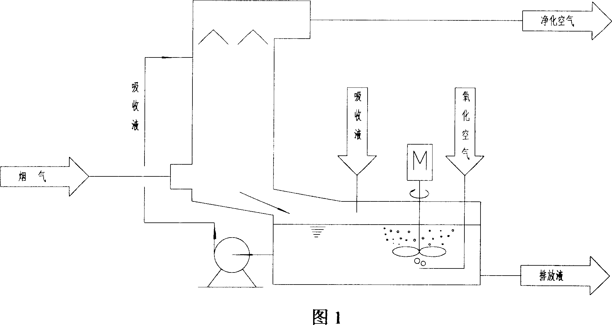
[0020] The liquid holding tank side-mounted flue gas desulfurization device of the present invention includes the following contents (see accompanying drawing 1):

[0021] (1) Flue gas desulfurization section (i.e. gas-liquid contact area);

[0022] (2) The liquid holding tank below the side of the flue gas desulfurization section (ie, the neutralization reaction zone);

[0023] (3) The circulation pump room directly below the flue gas desulfurization section.

[0024] Among them, the flue gas desulfurization section is installed on a platform constructed of concrete. The flue gas desulfurization section can use anti-corrosion concrete or anti-corrosion masonry structure, and can also use stainless steel or other metal materials with anti-corrosion lining (such as rubber lining), and anti-corrosion metal materials a...


PUM


Abstract

The invention relates to a liquid holdup side set flue gas desulfurization device made of gas desulfurization and side holding liquid slot. The smoke going into the bottom of the desulfurization section, contact with the top spraying absorption counter current to be removed by SO2 in the smoke, absorption liquid falling to the bottom of the desulfruization flowing back to the liquid holdup slot without liquid storing at the bottom, installing mixer on the top of the liquid holding slot, preventing the deposit of floating grains, blowing into oxidization air from the liquid holdup slot, with the oxidized gas emitted together with the purified smoke. The space right under the smoke desulfurization section is the circulating pump house.

Description

technical field [0001] The invention relates to a flue gas desulfurization device, in particular to a flue gas desulfurization device using lime, limestone powder, light-burned magnesium oxide powder and magnesite powder as desulfurizing agents. Background technique [0002] Lime, limestone powder, light-burned magnesia powder, and magnesite powder are the main desulfurization agents for flue gas desulfurization, especially lime and limestone powder are often used as flue gas desulfurization agents because of their low cost. Flue gas desulfurization equipment generally adopts flue gas spray absorption tower, such as the schematic diagram of absorption tower on pages 70 to 76 of "Coal-fired flue gas desulfurization and denitrification technology and engineering examples" published by Chemical Industry Press in April 2002. The upper part is the desulfurization section where the flue gas is in contact with the absorption liquid. The lower part of the absorption tower is the liq...

Claims


Application Information

Patent Timeline
Patent Type & Authority Applications(China)
IPC IPC(8): B01D53/78B01D53/50
Inventor 齐慧敏方向晨刘忠生彭德强
Owner CHINA PETROLEUM & CHEM CORP
Why Eureka
Try Eureka