Magnetoresistive effect element and magnetic memory

A technology of magnetoresistance effect element and magnetic memory, which is applied to devices applying electro-magnetic effect, static memory, digital memory information, etc., can solve the problem of difficulty in realizing large capacity, large writing current value, and insulation damage of tunnel insulating layer. Component damage, etc.

Inactive Publication Date: 2007-10-31
KK TOSHIBA
View PDF3 Cites 32 Cited by
  • Summary
  • Abstract
  • Description
  • Claims
  • Application Information

AI Technical Summary

Problems solved by technology

This MRAM has attracted attention as a high-speed nonvolatile random access memory, but there is a problem that, in the writing method using a current magnetic field, the writing current value is large, and it is difficult to increase the capac

Method used


Image

  • Magnetoresistive effect element and magnetic memory
  • Magnetoresistive effect element and magnetic memory
  • Magnetoresistive effect element and magnetic memory

Examples


no. 1 Embodiment approach

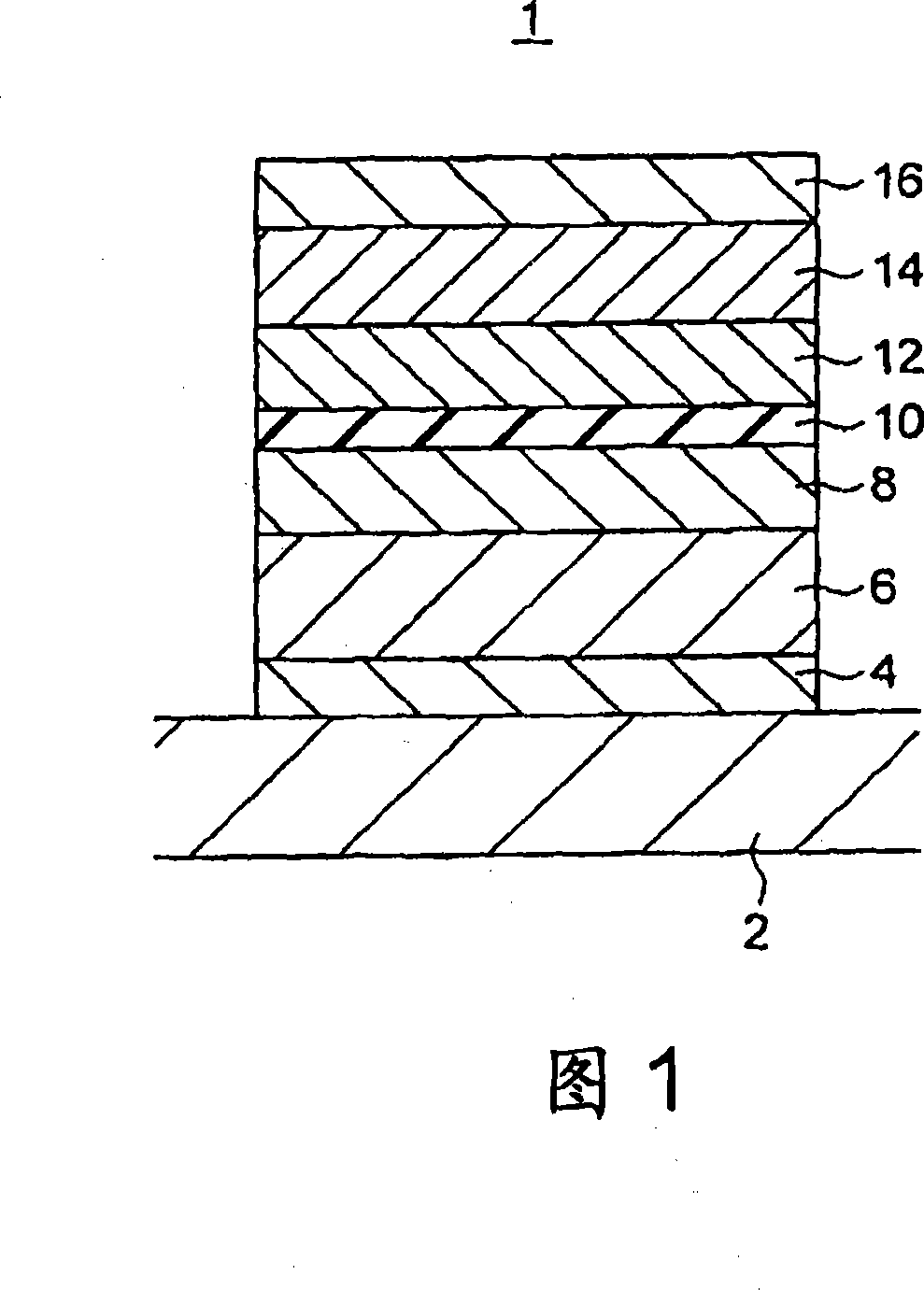
[0029] FIG. 1 shows a cross section of a magnetoresistance effect element according to a first embodiment of the present invention. The magnetoresistance effect element 1 of this embodiment is a lower fixed (bottom pin) type magnetoresistance effect element, comprising: a bottom layer 4 arranged on the lower electrode 2; an antiferromagnetic layer 6 arranged on the bottom layer 4; magnetization fixed layer 8 on the magnetic layer 6 and composed of a magnetization fixed ferromagnetic layer; tunnel insulating layer 10 provided on the magnetization fixed layer 8; provided on the tunnel insulating layer 10 and composed of a ferromagnetic layer whose magnetization direction is variable The magnetization free layer (magnetic recording layer) 12; the antiferromagnetic layer 14 provided on the magnetization free layer 12; the top cover (cap) layer 16 provided on the antiferromagnetic layer 14; and the cap layer 16 provided on the upper electrode (not shown). In addition, in this embo...

no. 2 Embodiment approach

[0054]Next, a magnetic memory according to a second embodiment of the present invention is shown in FIG. 7 . The magnetic memory of this embodiment has at least one memory cell provided in the intersection region of the bit line 30 and the word line 40 . The above-mentioned memory cell has the lower fixed magnetoresistance effect element 1 of the first embodiment shown in FIG. 1 and the select transistor 60 for both writing and reading, and forms one bit. The selection transistor 60 has a source region 61 , a gate region 62 and a drain region 63 . One terminal of the magnetoresistance effect element 1 is connected to the extraction electrode 20 , and the other terminal is connected to the bit line 30 via the metal hard mask or the via 25 . The extraction electrode 20 is connected to the source region 61 of the selection transistor 60 via the connection portion 50 . The word line 40 is connected to the drain region 63 of the selection transistor 60 . In addition, the selecti...

no. 3 Embodiment approach

[0060] Next, a magnetic memory according to a third embodiment of the present invention is shown in FIG. 11 . The magnetic memory of this embodiment has at least one memory cell, and the memory cell is provided on the bit line 30 1 、30 2 in the intersection region with the word line 40 . The above-mentioned memory cell has the bottom pinned magnetoresistance effect element 1 of the first embodiment shown in FIG. 1 1 ,1 2 The select transistor 60 used for both writing and reading forms 1 bit. The selection transistor 60 has a source region 61 , a gate region 62 and a drain region 63 . Magnetoresistance effect element 1 1 One terminal of is connected to the lead-out electrode 20, and the other terminal is connected via a metal hard mask or a via 25 1 with bit line 30 1 connect. The extraction electrode 20 is connected to the source region 61 of the selection transistor 60 via the connection portion 50 . The word line 40 is connected to the drain region 63 of the selecti...


PUM

PropertyMeasurementUnit
Thicknessaaaaaaaaaa

Abstract

It is possible to provide a magnetoresistive effect element and a magnetic storage which has thermal stability even if it is made fine and in which the magnetization in the magnetic recording layer can be inverted at a low current density. A magnetoresistive effect element includes: a magnetization pinned layer having a magnetization pinned in a direction; a magnetization free layer of which magnetization direction is changeable; a tunnel barrier layer provided between the magnetization pinned layer and the magnetization free layer; a first antiferromagnetic layer provided on the opposite side of the magnetization pinned layer from the tunnel barrier layer; and a second antiferromagnetic layer which is provided on the opposite side of the magnetization free layer from the tunnel barrier layer and which is thinner in thickness than the first antiferromagnetic layer, wherein the direction of the magnetization of the free magnetization layer can be converted by pouring an electron whose polarity is changed in spin polarization into the free magnetization layer.

Description

[0001] Cross References to Related Applications [0002] This application is based upon and claims the benefit of priority from prior Japanese Patent Applications Nos. 2006-126682 and 2006-244881 filed in Japan on April 28, 2006 and September 8, 2006, the entire contents of which are incorporated herein by reference Applying. technical field [0003] The present invention relates to a magnetoresistance effect element and a magnetic memory. Background technique [0004] It has been proposed to use a magnetoresistance effect element using a magnetic film for a magnetic head, a magnetic sensor, and the like, and for a solid magnetic memory (magnetoresistance effect memory: MRAM (Magnetic Random Access Memory)). [0005] MRAM uses a tunneling magnetoresistance effect element (Tunneling Magneto-Resistance effect: TMR element) in which a tunnel insulating layer is inserted between two ferromagnetic layers, one being a magnetic recording layer and the other being a magnetization f...

Claims


Application Information

Patent Timeline
IPC IPC(8): G11B5/39G11C11/15H01L43/00
Inventor 齐藤好昭杉山英行井口智明
Owner KK TOSHIBA
Why Eureka
Try Eureka