Optical detector for a particle sorting system

An optical detection and detector technology, applied in the field of particle systems, can solve problems such as difficulty in observing low-brightness level signals, inaccurate optical detection systems, and poor results

Inactive Publication Date: 2007-11-14
CYTONOMEST
View PDF6 Cites 12 Cited by
  • Summary
  • Abstract
  • Description
  • Claims
  • Application Information

AI Technical Summary

Problems solved by technology

[0005] Traditional inspection systems have significant disadvantages
For example, existing optical detection systems are sometimes imprecise and provide poor results due to the difficulty of observing low light level signals from fluorescent lab

Method used


Image

  • Optical detector for a particle sorting system
  • Optical detector for a particle sorting system
  • Optical detector for a particle sorting system

Examples


Embodiment Construction

[0023] The present invention provides an optical system for monitoring and detecting particle flow through an array of channels. The invention will be described below with reference to various exemplary embodiments. Those skilled in the art will appreciate that the present invention is applicable to many different uses and embodiments, and that the present invention is not particularly limited in application to the specific embodiments described herein.

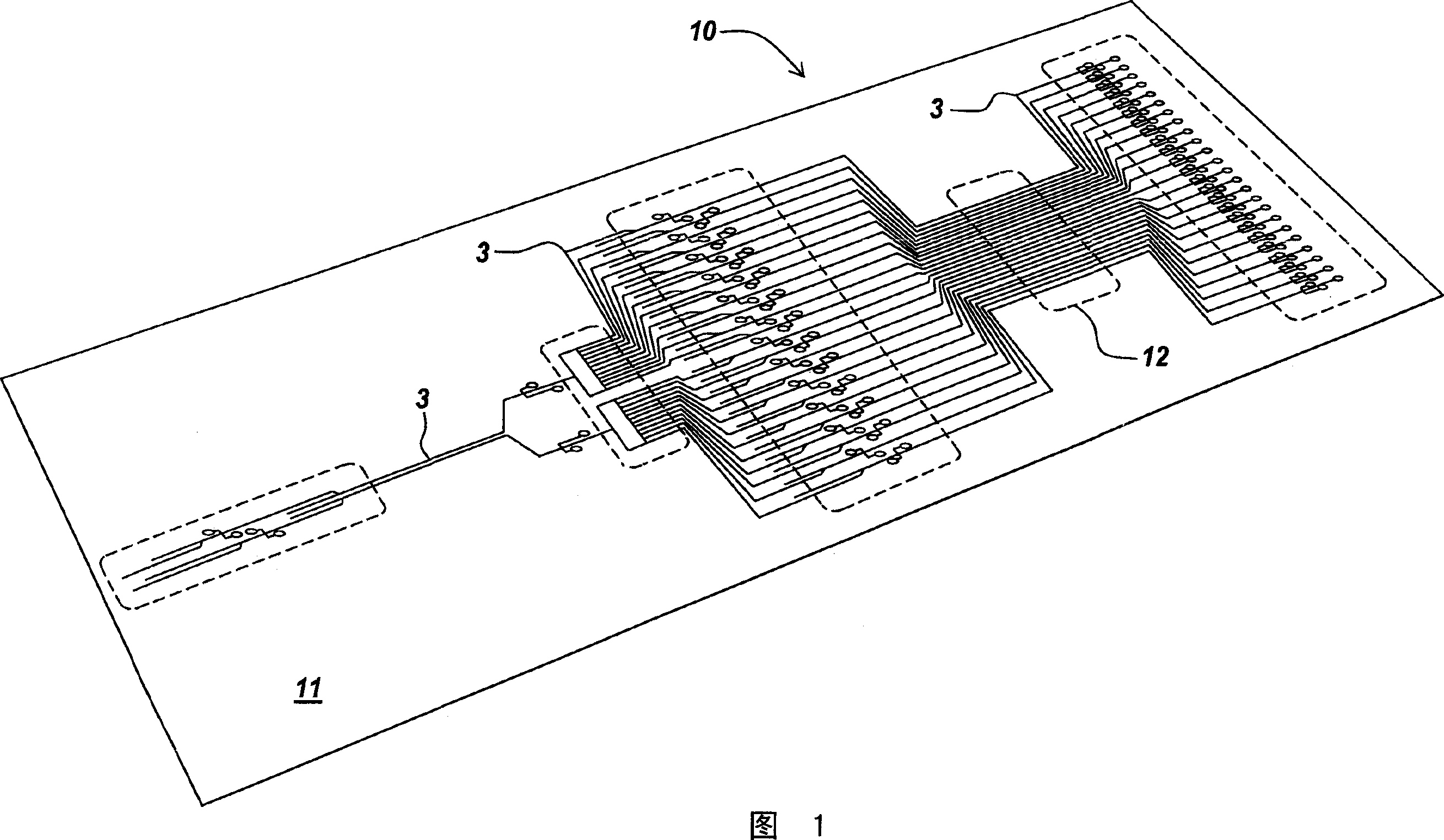
[0024] FIG. 1 illustrates a microfluidic system 10 suitable for practicing an example embodiment of the present invention, the microfluidic system including a plurality of channels for conveying substances such as particles or cells therethrough. The example microfluidic system 10 comprises a substrate 1 having a plurality of channels, such as microchannels 3, disposed therein. These channels transport fluids and / or particles through the microfluidic system 10 for processing, manipulating and / or performing any suitable manip...


PUM


Abstract

To provide a display device having a shift register circuit capable of suppressing a current consumption from increasing. This display device is equipped with a shift register 30m. The shift register 30mincludes a p-channel transistor PT3 which is connected to an HVSS side, a 1st circuit part 31mwhich is connected to a clock signal line, a p-channel transistor PT8 which is connected to the HVSS side, and a 2nd circuit part 32mwhich is connected to the clock signal line. The p-channel transistor PT3 turns on in response to a clock signal HCLK. The 1st circuit part 31mhas a p-channel transistor PT5 which turns on in response to the output signal SRm+1(1st signal) of a shift regsiter 30m+1of a trailing stage to supply the clock signal HCLK to the p-channel transistor PT3. The p-channel transistor PT8 turns on in response to the clock signal HCLK. A 2nd circuit part 32mhas a p-channel transistor PT10 which turns on in response to the output siganl SRm-1(2nd singal) of a shift register circuit 30m-1of a precedent stage to supply the clock signal HCLK to the p-channel transistor PT8.

Description

[0001] Related Patent Applications [0002] This application claims priority to U.S. Provisional Patent Application Serial No. 60 / 495,374, filed August 14, 2003, and U.S. Patent Application Serial No. XX / XXX,XXX, filed August 9, 2004, which The contents are incorporated by reference in their entirety. technical field [0003] The present invention relates to systems and methods for monitoring particles flowing through a channel. Background technique [0004] In systems such as microfluidic systems that transport particles through one or more channels, optical systems may be used to monitor, analyze, or detect the particles. Optical systems are useful, for example, in particle sorting systems that sort a stream of particles flowing through one or more channels based on predefined characteristics. [0005] Traditional detection systems have significant disadvantages. For example, existing optical detection systems are sometimes inaccurate and provide poor results due to the...

Claims


Application Information

Patent Timeline
IPC IPC(8): G01N21/88G01N21/00G01N1/00
Inventor J·R·吉尔伯特E·辛诺夫斯基M·德什潘德
Owner CYTONOMEST
Why Eureka
Try Eureka