Fiber magnetic optical probe device and its usage system
A magneto-optical and optical fiber technology, applied in the optical field, can solve problems such as near-zero desensitization, and achieve the effect of easy installation and small size
- Summary
- Abstract
- Description
- Claims
- Application Information
AI Technical Summary
Problems solved by technology
Method used
Image

Examples
Embodiment 1
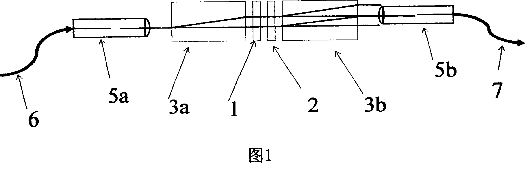
[0078] According to Fig. 1, the optical fiber magneto-optical probe device of the present embodiment comprises input optical fiber 6, input light collimator 5a, first polarization beam splitter 3a, Faraday magneto-optic rotator 1, 1 / 2 wave plate 2, the second polarization Beam splitter 3b, output light collimator 5b and output optical fiber 7, as shown in Figure 1, the first polarized beam splitter 3a and the second polarized beam splitter 3b in the present embodiment adopt the birefringent crystal polarization splitter of flat plate type uniaxial The device can be made of YVO4 crystal, which can separate two mutually orthogonal polarized lights at a certain distance in space, and the light beam is divided into two beams of parallel lights after passing through the first polarization beam splitter 3a, and their polarization states are mutually orthogonal , the second polarization beam splitter 3b is exactly the same as the first polarization beam splitter 3a, so it can combine ...
Embodiment 2
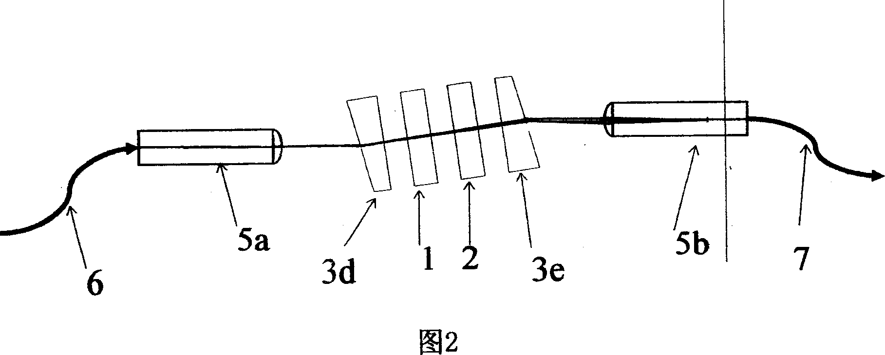
[0093] As shown in FIG. 2 , the difference between this embodiment and Embodiment 1 is that in this embodiment, a first polarization beam splitter 3 d and a second polarization beam splitter 3 e of a wedge-shaped polarization beam splitter are used.
[0094] In this embodiment, the first polarizing beam splitter 3d and the second polarizing beam splitter 3e are also made of uniaxial crystals, which can separate two mutually orthogonal polarized lights at a certain angle. After the light passes through the first polarizing beam splitter 3d, it is divided into two beams whose polarization planes are orthogonal to each other, and the propagation directions of the two beams form a small angle. After they arrive at the second polarization beam splitter 3e, the direction of propagation of the component whose polarization plane is turned 90° relative to the original polarization plane produced by the first polarization beam splitter 3d in each beam will become consistent, although the...
Embodiment 3
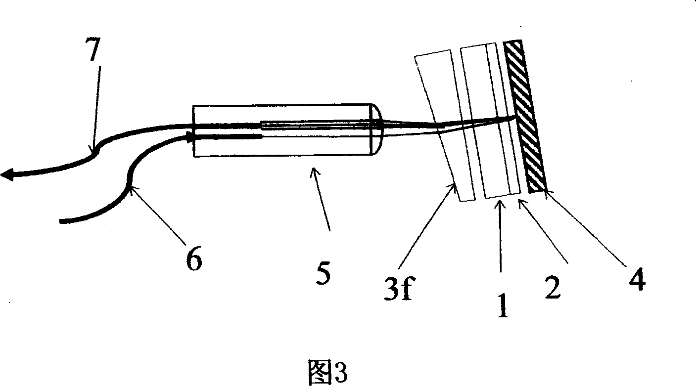
[0096] According to Fig. 3, the optical fiber magneto-optical probe device of the present embodiment comprises input optical fiber 6, output optical fiber 7, optical fiber optical collimator 5c, wedge plate type polarization beam splitter 3f, Faraday magneto-optical rotator 1, 1 / 4 wave plate 2b and reflector 4, input optical fiber 6 and output optical fiber 7 are all conducted with fiber optic collimator 5c, in the present embodiment, the crystal optical axis of 1 / 4 wave plate 2b and Faraday magneto-optical rotator 1 two beam output The orthogonal polarization planes of light are at 22.5° or 67.5°.
[0097] As shown in FIG. 3, input fiber 6 introduces light into fiber optic collimator 5c.
[0098] As shown in FIG. 3 , the fiber optic collimator 5c collimates the light and then transmits it to the polarization beam splitter 3f.
[0099] As shown in FIG. 3 , the polarization beam splitter 3 f splits the light into two beams of light, and the two beams of light are polarized lig...
PUM
 Abstract
Description
Claims
Application Information
 - R&D
- Intellectual Property
- Life Sciences
- Materials
- Tech Scout
- Unparalleled Data Quality
- Higher Quality Content
- 60% Fewer Hallucinations
Browse by: Latest US Patents, China's latest patents, Technical Efficacy Thesaurus, Application Domain, Technology Topic, Popular Technical Reports.
© 2025 PatSnap. All rights reserved.Legal|Privacy policy|Modern Slavery Act Transparency Statement|Sitemap|About US| Contact US: help@patsnap.com