

Silencer and respirator therewith
A noise reduction device and fan technology, applied in the direction of noise reduction devices, respirators, mechanical equipment, etc., can solve the problems of limited sound reduction means, achieve the effect of reducing low-frequency noise, small size, and simple structure
- Summary
- Abstract
- Description
- Claims
- Application Information
AI Technical Summary
Problems solved by technology
Method used
Image

Examples
Embodiment Construction
[0033] A preferred embodiment of the noise reduction device of the present invention is shown in Figure 8. The interior of the noise reduction device is provided with a spiral air passage, and the air inlet 1 of the spiral air passage is located at the outer end of the spiral air passage. The noise reduction device includes a main body 10 and an upper The cover 9 and the upper cover 9 are buckled on the main body 10, forming a plane spiral air passage between them.
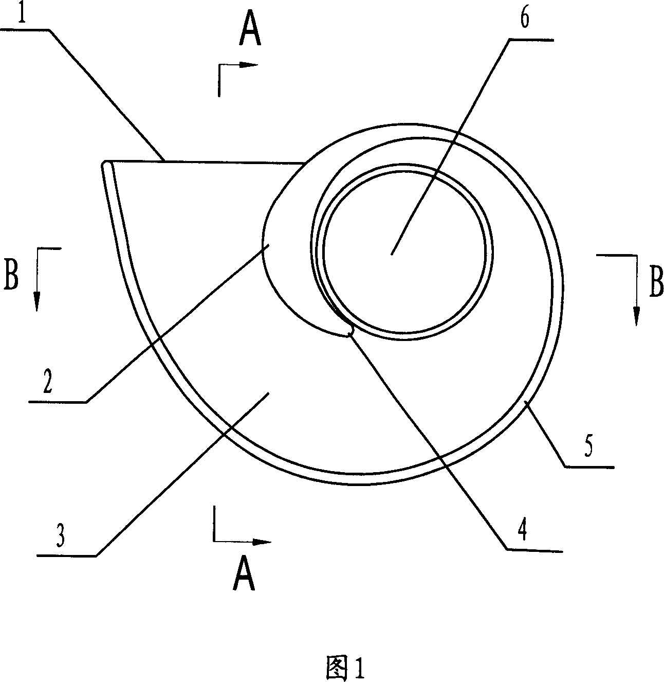
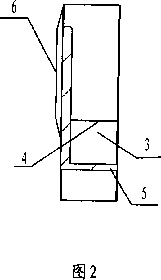
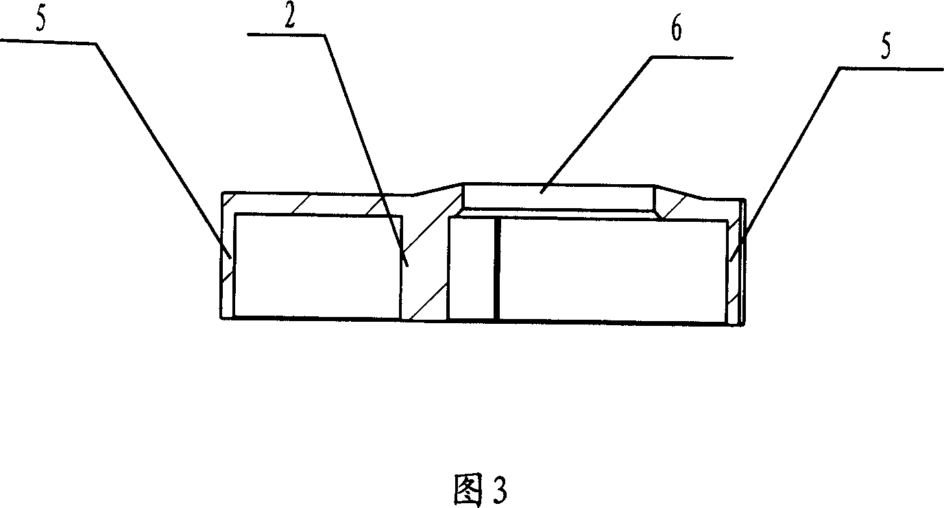
[0034] The main body 10 of the muffler is shown in Figures 1, 2, 3 and 4. The air outlet 6 of the spiral air passage 3 is located at the center of the inner end of the spiral air passage 3 and is perpendicular to the spiral plane of the spiral air passage 3. The air inlet 1 of the spiral air passage 3 is along the tangent direction of the helix of the spiral air passage 3 . The helical shape of the spiral air passage 3 can be an involute or an equidistant helix or an Archimedes helix, and can also be other helical...
PUM
 Abstract
Description
Claims
Application Information