Semiconductor wafer welding material projected block structure and its production

A technology of solder bumps and manufacturing methods, which is applied in semiconductor/solid-state device manufacturing, semiconductor devices, semiconductor/solid-state device components, etc., can solve the problems of poor consistency of solder bump height and volume, and achieve consistent height and volume Easy to control, high density of solder joints, beneficial to miniaturization

Active Publication Date: 2007-11-21
SEMICON MFG INT (SHANGHAI) CORP +1
View PDF1 Cites 33 Cited by
  • Summary
  • Abstract
  • Description
  • Claims
  • Application Information

AI Technical Summary

Problems solved by technology

[0005] In view of this, the object of the present invention is to provide a semiconductor chip solder bump structure and manufacturing method thereof, adopt the design of planarized surface multilayer ...

Method used


Image

  • Semiconductor wafer welding material projected block structure and its production
  • Semiconductor wafer welding material projected block structure and its production
  • Semiconductor wafer welding material projected block structure and its production

Examples


Embodiment Construction

[0054] The specific embodiments of the present invention will be described in detail below in conjunction with the accompanying drawings.

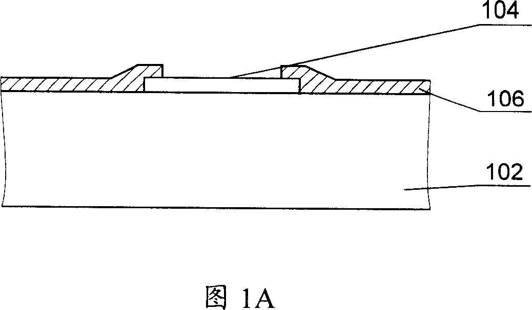
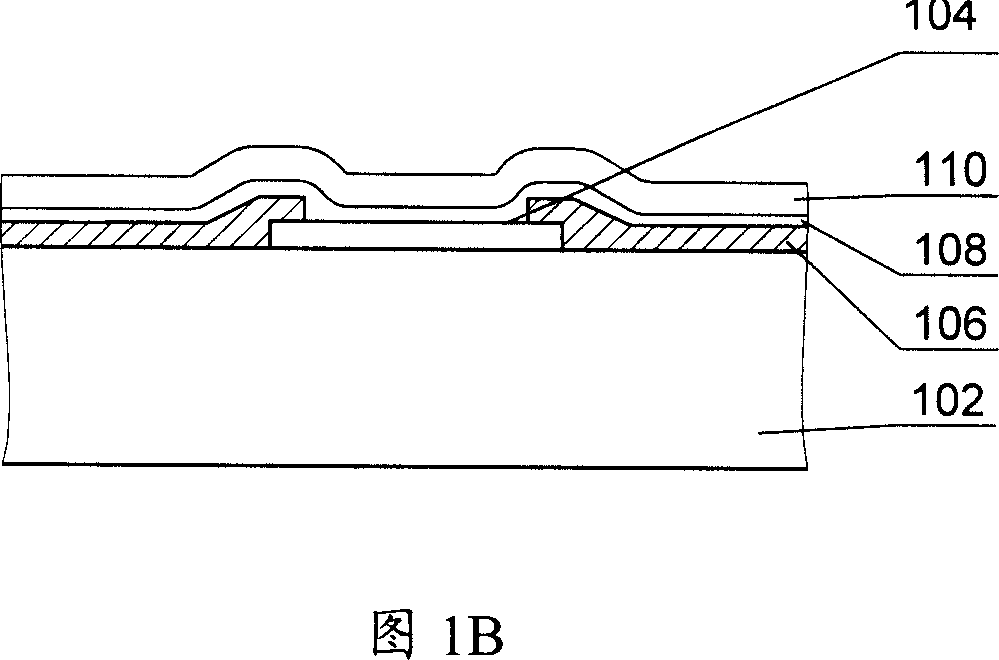
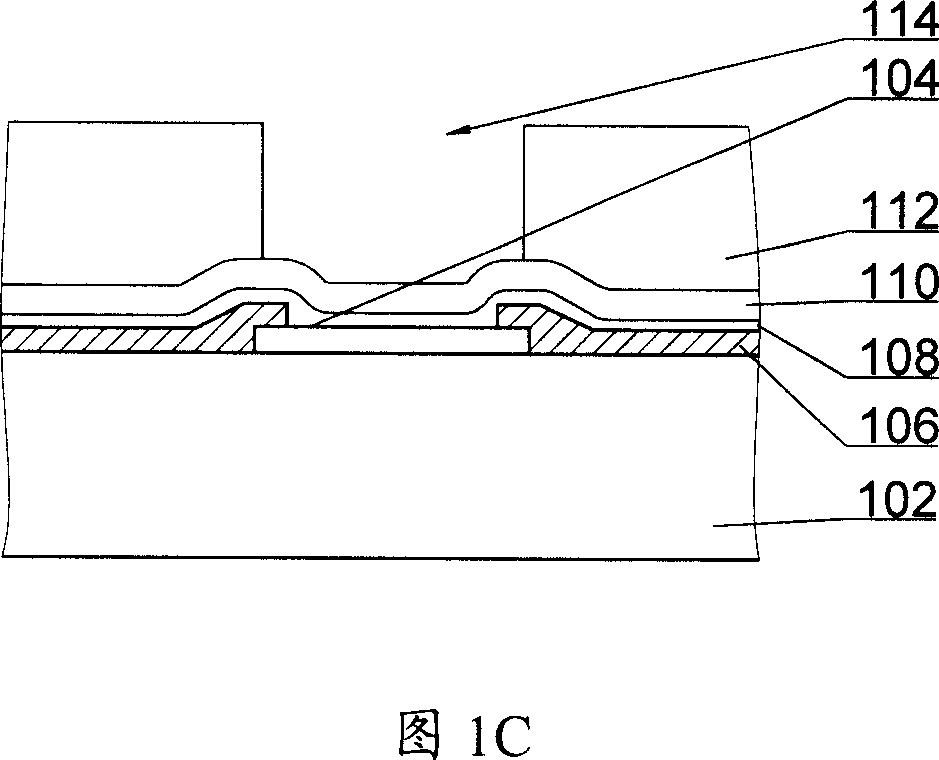
[0055] The solder bump structure of the semiconductor wafer and the manufacturing method thereof of the present invention planarize the bonding pad (ie pad) and the passivation layer through chemical mechanical polishing (CMP), so that the UBM layer formed thereon has a flat structure. The UBM layer structure adopts a hybrid laminated structure of a heat-resistant metal layer (refractory metal layer), a metal wetting layer (wetting layer), an adhesion layer and a barrier layer. Fig. 2 is a schematic diagram of the solder bump structure of the semiconductor wafer according to the present invention. As shown in FIG. 2, the solder bump structure of the present invention includes a pad 304 and a passivation layer 306 formed on a substrate 302. Preferably, the bottom layer of the pad 304 may have a stabilizing pad 303 to enhance the mechanical ...


PUM

PropertyMeasurementUnit
Thicknessaaaaaaaaaa
Thicknessaaaaaaaaaa
Diameteraaaaaaaaaa

Abstract

This is a convex structure for semi-conducting wafer and its process method. Make a flat joint plate and passive layer on the surface of the underlay, then condensate a multi-layer metal coating to increase the refluence height of the electrode on the convex and volume coherence and purity.

Description

technical field [0001] The invention relates to semiconductor device manufacturing technology, in particular to a semiconductor wafer bump structure used in microelectronic circuits for flip chip packaging (Flip Chip), wafer level packaging (WLP) and other leading packaging technologies and a manufacturing method thereof. Background technique [0002] With the rapid development of the semiconductor device manufacturing industry, the semiconductor device has a deep submicron structure, and a semiconductor integrated circuit (IC) contains a huge number of semiconductor devices. In this large-scale integrated circuit, the manufacturing technology of microelectronic integrated circuits on semiconductor wafers includes the device manufacturing in the front end and the interconnection structure in the back end for high-performance, high-density interconnection between components to achieve the required functions manufacturing. Integrated circuits on a semiconductor wafer typicall...

Claims


Application Information

Patent Timeline
IPC IPC(8): H01L23/485H01L21/28H01L21/60
CPCH01L24/11H01L2224/11H01L2924/14H01L2924/351H01L2924/00H01L2924/00012
Inventor 王津洲
Owner SEMICON MFG INT (SHANGHAI) CORP
Why Eureka
Try Eureka