Method for processing frostbite prevention and quick startup of hydrogen stack
A processing method and technology of hydrogen stack, applied in circuits, fuel cells, electrical components, etc., can solve problems such as environmental adaptability gaps
- Summary
- Abstract
- Description
- Claims
- Application Information
AI Technical Summary
Problems solved by technology
Method used
Image
Examples
Embodiment 1
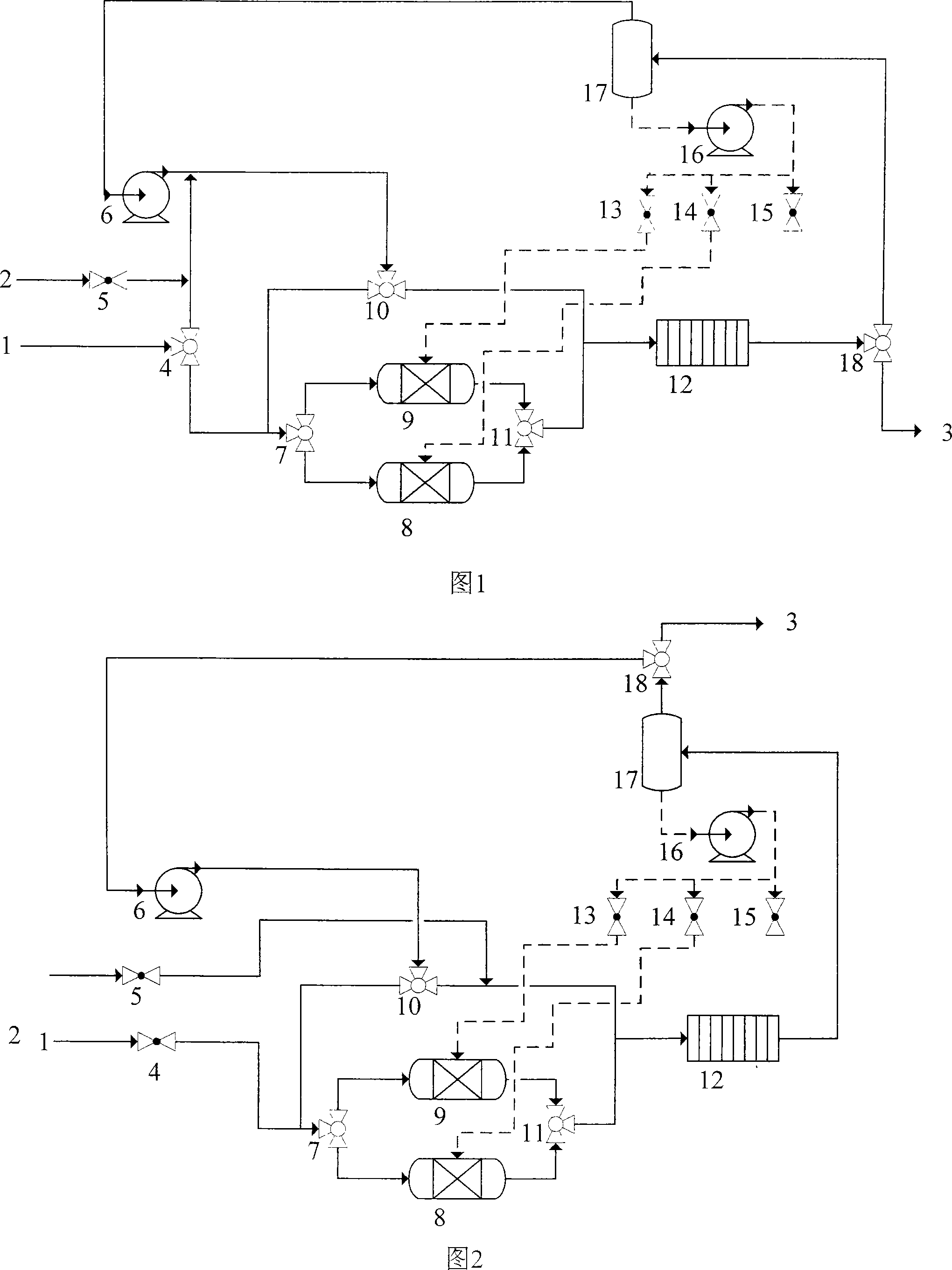
[0020] The hydrogen stack has a fuel hydrogen circulation loop and an oxidant loop. This example takes the hydrogen gas circuit as an example, and the oxidant circuit is similar to this. Refer to Figure 1 for the structure, and refer to the accompanying drawings for the meanings of the symbols.
[0021] When shutting down, for the hydrogen stack 12, the gas is first circulated through the circulation pump 6, free water in the system is purged, and separated in the water separator 12. Then or at the same time, the hydrogen stack 12 outputs electric energy to consume the hydrogen in the circulation system. Electric energy can be exported to the battery, or directly heat the gas heater (not shown in the figure).
[0022] For the high-pressure system, when the pressure is reduced to close to the ambient pressure, an inert gas, such as nitrogen, is introduced, and the pressure of the control system is slightly higher than the ambient pressure. The nitrogen is provided by the nitro...
Embodiment 2
[0031] Embodiment 2 is shown in Figure 2. Wherein the hydrogen source 2 reaches the wet exchanger I or II through the valve 4, the pipeline, and the switching valve 7. The nitrogen source 2 is controlled by the valve 5 and can directly reach the hydrogen stack 12 through the pipeline. The working gas from the hydrogen stack goes through the pipeline to the water separator 17. If the gas contains liquid water, the gas and liquid are separated in the water separator. If the gas needs to be discharged, the switching valve 18 is used to discharge the gas to the tail gas processed in Processor 3. There is a drain valve (not shown in the figure) at the bottom of the water distributor, and the liquid water is under the control of the system, through the valves 13, 14, 15, and the pump 16 is used to selectively inject the wet exchanger I, II or other water devices including exhaustion. to the outside world.
[0032] Others are similar to Example 1.
PUM
 Abstract
Description
Claims
Application Information
 - R&D
- Intellectual Property
- Life Sciences
- Materials
- Tech Scout
- Unparalleled Data Quality
- Higher Quality Content
- 60% Fewer Hallucinations
Browse by: Latest US Patents, China's latest patents, Technical Efficacy Thesaurus, Application Domain, Technology Topic, Popular Technical Reports.
© 2025 PatSnap. All rights reserved.Legal|Privacy policy|Modern Slavery Act Transparency Statement|Sitemap|About US| Contact US: help@patsnap.com

