Power factor correcting converter

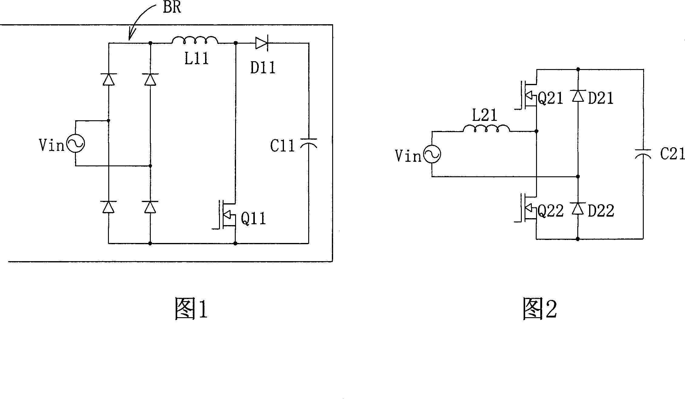
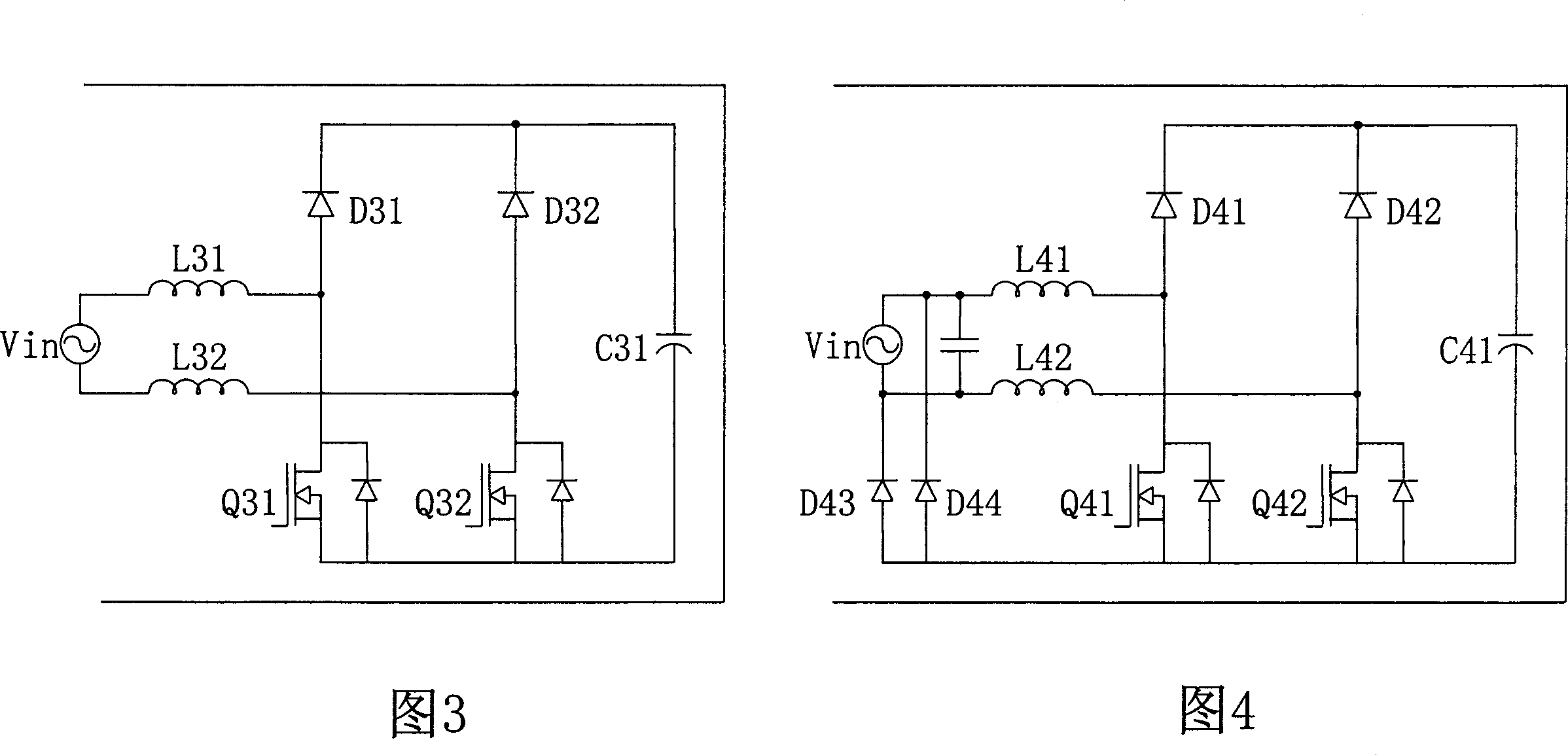
A power factor correction and converter technology, which is applied in the direction of output power conversion device, high-efficiency power electronic conversion, DC power input conversion to DC power output, etc., can solve the waste of circuit space, bulky, boost inductor L41 and Issues such as low utilization of L42

Active Publication Date: 2007-12-05
DELTA ELECTRONICS INC
View PDF0 Cites 38 Cited by
  • Summary
  • Abstract
  • Description
  • Claims
  • Application Information

AI Technical Summary

Problems solved by technology

Nevertheless, the boost inductors L41 and L42 of the converter in Fig. 4 are bulky, resulting in a waste of circuit space.
In addition, during the time period of the input voltage Vin, the boost inductors L41 and L42 work alternately, so the utilization ratio of the boost inductors L41 and L42 is very low, which also limits the improvement of power density

Method used


Image

  • Power factor correcting converter
  • Power factor correcting converter
  • Power factor correcting converter

Examples


Embodiment Construction

[0098] Preferred embodiments embodying the features and advantages of the present invention will be described in detail in the ensuing description. It should be noted that like element numbers refer to like elements. It should be understood that the present invention can have various changes in different structures, all of which do not depart from the scope of the present invention, and the description and reference signs therein are used as illustrations in nature, not to limit the present invention .

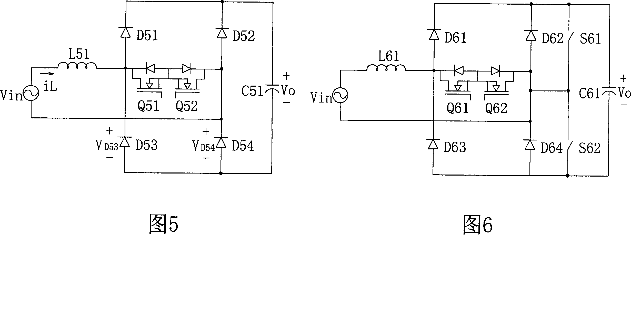
[0099]FIG. 5 shows a schematic circuit diagram of the first embodiment of the bridgeless power factor converter of the present invention. The converter of FIG. 5 includes a boost inductor L51, which is coupled to the input terminal, and bidirectional switches Q51 and Q52, which are implemented by metal-oxide-semiconductor field-effect transistors (MOSFETs) and connected in series with the boost inductor L51. . The converter in FIG. 5 also includes a first series rectifying ...


PUM


Abstract

The invention is a bridge-free power factor correction (PFC) converter able to reduce common code noises and increase power density, comprising: boost inductor coupled to input end; two-way switch connected in series with the boost inductor and having junction node coupled between the boost inductor and two-way switch; second series rectifier circuit, having junction node coupled to the two-way switch; and output capacitor connected in parallel with the second series rectifier circuit; where the second series rectifier circuit is composed of slow recovery diode and the first series rectifier circuit is composed of fast recovery diode. Thus, the invention can reduce common mode noises in the converter and increase the power density of the converter.

Description

technical field [0001] The present invention relates to a power factor correction converter, more particularly, the present invention relates to a bridgeless power factor correction converter capable of reducing common-mode noise interference and improving power density. Background technique [0002] A switching mode power supply is a power conversion circuit that uses a switch to convert an input voltage waveform into a specific output voltage waveform. A boost converter is an example of a switching power supply that provides powerfactor correction and total harmonic distortion reduction to an input voltage, and converts the input voltage into a stable and Adjustable output voltage. [0003] Figure 1 shows a schematic circuit diagram of a common power factor correction conversion boost converter (PFC boostconverter). In FIG. 1 , a bridge rectifier (bridge rectifier) ​​BR is coupled to the input AC voltage Vin for converting the input AC voltage Vin into a full-wave rectif...

Claims


Application Information

Patent Timeline
Patent Type & Authority Applications(China)
IPC IPC(8): H02J3/18H02M7/12
CPCH02M1/4225H02M3/1584Y02E40/30Y02B70/10Y02P80/10H02M1/0085
Inventor 刘腾辛晓妮曾剑鸿应建平
Owner DELTA ELECTRONICS INC
Why Eureka
Try Eureka