RF antenna, electronic label and method for making RF antenna

A radio frequency antenna, electronic label technology, applied in the direction of antenna, loop antenna, antenna parts, etc., can solve the problems of increased load of conductive sheet, poor bending characteristics of label, separation of carrier and coil, etc., to reduce thickness, reduce load, Connection for reliable effects

Inactive Publication Date: 2007-12-12
陈栋栋
View PDF0 Cites 15 Cited by
  • Summary
  • Abstract
  • Description
  • Claims
  • Application Information

AI Technical Summary

Problems solved by technology

[0007] The above-mentioned conductive sheet is usually called a carrier. The chip is placed on this carrier and then riveted to the wire end. This process is purely because the original chip manufacturer is an expedient measure for the expensive flip-packaging equipment in the early stage, because the contact surface is too large to cause the label to be damaged. The bending characteristics are very poor, and it is easy to cause the carrier and the coil to separate during use, which not only has high cost but also low yield
[0008] In actual use, users often need the thinner the electronic tag, the better, but this kind of electronic tag that uses a copper-clad plate to make the antenna, because the conductive sheet is used to connect the wire end of the antenna to make the bridge part of the antenna, the conductive sheet It itself wil

Method used


Image

  • RF antenna, electronic label and method for making RF antenna
  • RF antenna, electronic label and method for making RF antenna
  • RF antenna, electronic label and method for making RF antenna

Examples


Embodiment approach 2

[0062] Embodiment 6 of the radio frequency antenna As shown in Figure 10, the coil 1001 is approximately circular, the position 1002 where the integrated circuit chip is installed is close to the coil 1001, and the distance between the two ends of the head and tail wire ends 1003 connected by the bridge is shorter than that of the embodiment of the radio frequency antenna. The second is to be close.

[0063] Embodiment 7 of the radio frequency antenna is shown in Figure 11, the coil 1101 is approximately circular, the part where the integrated circuit chip is installed 1102 connected to the coil is close to the coil 1101, and the other part is located in the center of the coil, and the head and tail ends connected by bridges The distance between the two ends of 1103 is closer than that in Embodiment 2 of the radio frequency antenna.

[0064] Embodiment 8 of the radio frequency antenna As shown in Figure 12, the coil 1201 is approximately circular, the position 1202 where the i...

specific Embodiment approach

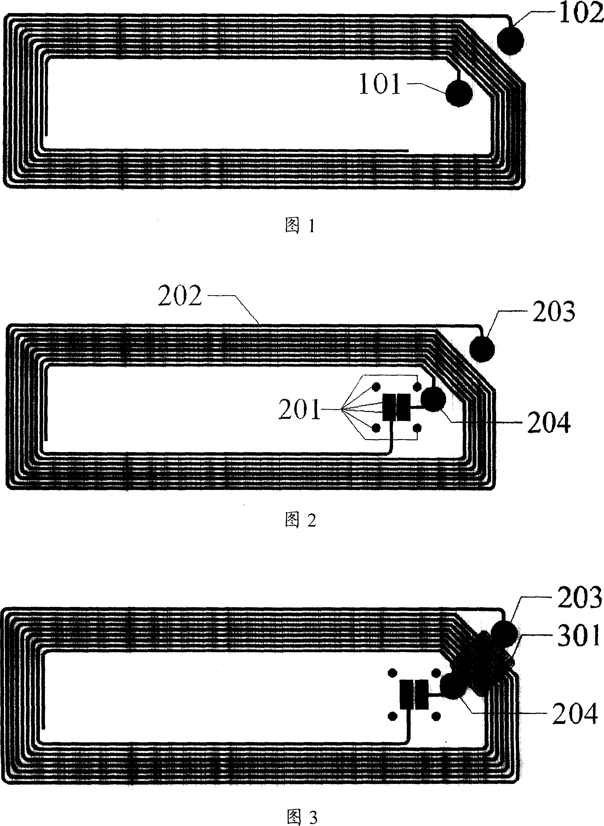
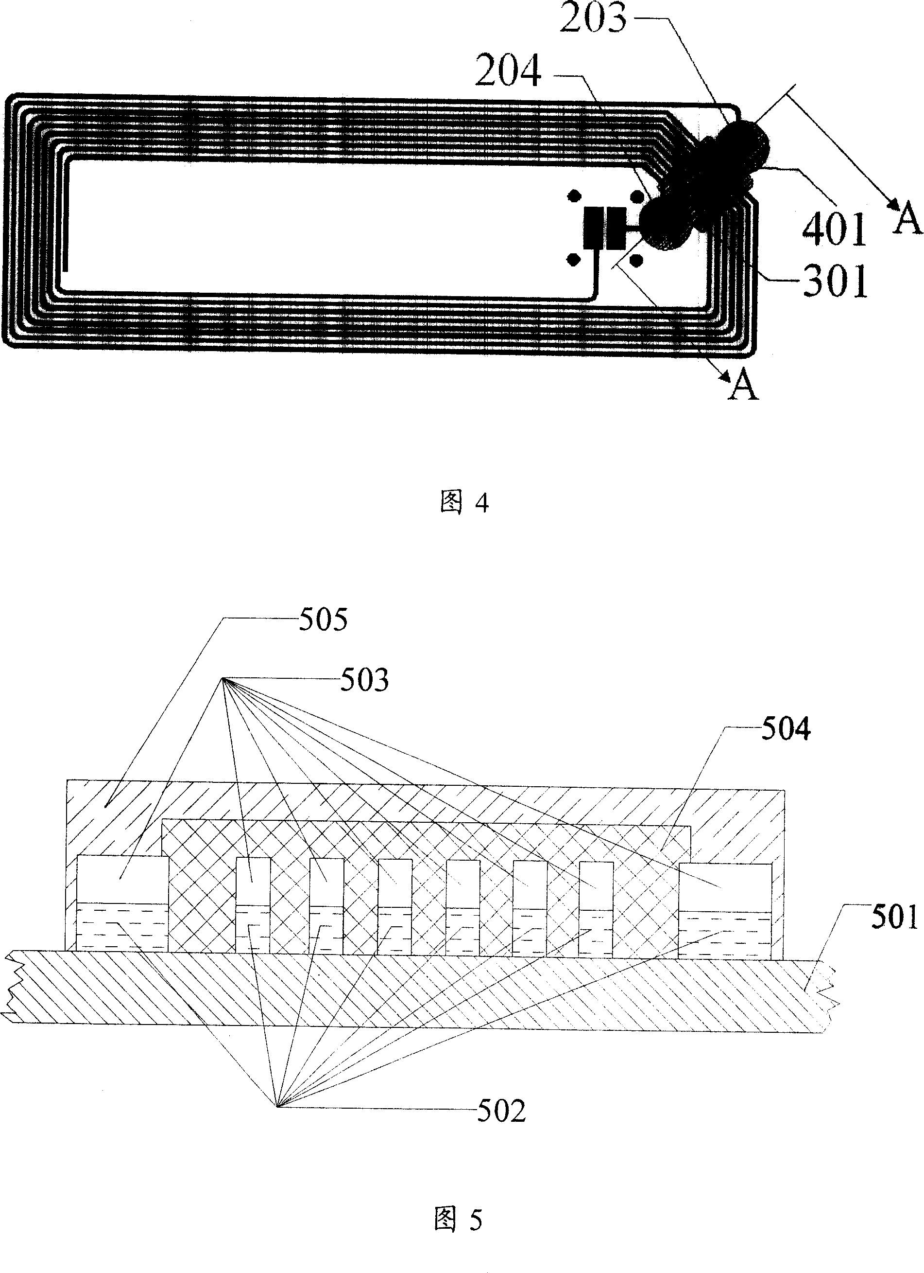
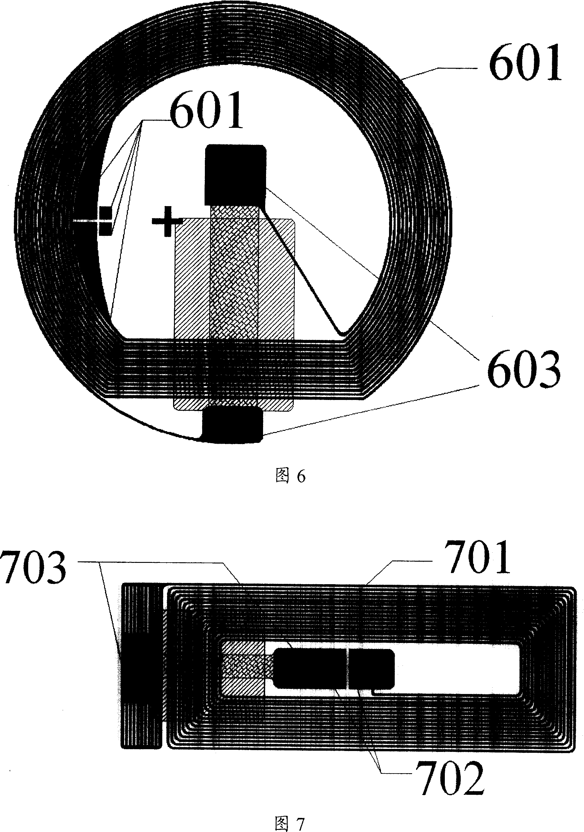
[0073] Embodiment 2 of the radio frequency antenna of the electronic tag is shown in Figure 6;

[0074] The third embodiment of the radio frequency antenna of the electronic tag is shown in Figure 7;

[0075] Embodiment 4 of the radio frequency antenna of the electronic tag is shown in Figure 8;

[0076] Embodiment five of the radio frequency antenna of the electronic tag is shown in Figure 9;

[0077] Embodiment six of the radio frequency antenna of the electronic tag is shown in Figure 10;

[0078] Embodiment 7 of the radio frequency antenna of the electronic tag is shown in Figure 11;

[0079] The eighth embodiment of the radio frequency antenna of the electronic tag is shown in Figure 12;

[0080] Embodiment 9 of the radio frequency antenna of the electronic tag is shown in Figure 13;

[0081] Embodiment 10 of the radio frequency antenna of the electronic tag is shown in Figure 14;

[0082] The eleventh embodiment of the radio frequency antenna of the electronic tag i...


PUM


Abstract

The invention discloses a method of producing radio-frequency antenna which includes: etching loop and position for integrated circuit which is connected with loop; producing gap bridge of said antenna to accomplish production of radio-frequency antenna. The invention also discloses a radio-frequency antenna which includes loop, Gap Bridge, insulating layer, and position for integrated circuit, said position for integrated circuit is connected with loop. The invention also discloses an electronic mark which adopts said radio-frequency antenna. By adopting the invention, thickness of electronic mark can be decreased effectively; reliability of integrated circuit chip, Gap Bridge and antenna connection can be increased.

Description

technical field [0001] The invention relates to the technical field of electronic tags, in particular to a method for manufacturing a radio frequency antenna by using a resin single panel, and a radio frequency antenna and an electronic tag manufactured by using a resin single panel. Background technique [0002] With the rapid development of automatic identification technology, the application of electronic tags using radio frequency identification (Radio Frequency Identification, RFID) technology has become more and more extensive, in logistics and non-contact integrated circuit (Integrated Circuit, IC) cards, etc. all play an important role. [0003] Any electronic tag includes the RF antenna part and the RF IC chip part connected to the RF antenna. There are many ways to make the RF antenna, such as using copper clad plate, enameled wire winding, and screen printing. [0004] Among them, using copper-clad boards to make radio-frequency antennas is a relatively common ma...

Claims


Application Information

Patent Timeline
IPC IPC(8): H01Q1/00H01Q1/38H01Q7/00H05K3/12G06K19/07
Inventor 陈栋栋
Owner 陈栋栋
Why Eureka
Try Eureka