Data transfer system and data processing apparatus

A data processing device and data transmission technology, applied in the direction of digital transmission system, transmission system, synchronization device, etc., can solve the problems of increased LSI power consumption, increased LSI area, reduced working time, etc., and achieve the effect of improving the data transmission rate

Inactive Publication Date: 2007-12-12
PANASONIC CORP
View PDF1 Cites 0 Cited by
  • Summary
  • Abstract
  • Description
  • Claims
  • Application Information

AI Technical Summary

Problems solved by technology

[0004] However, when the operating clock rate is increased, the power consumption of the LSI increases
In battery-operated devices such as mobile phones, increased power consumption results in reduced operating time and is therefore undesirable
In addition, the increase in the number of data signal lines undesirably leads to an increase in the area of ​​the LSI

Method used


Image

  • Data transfer system and data processing apparatus
  • Data transfer system and data processing apparatus
  • Data transfer system and data processing apparatus

Examples


no. 1 example

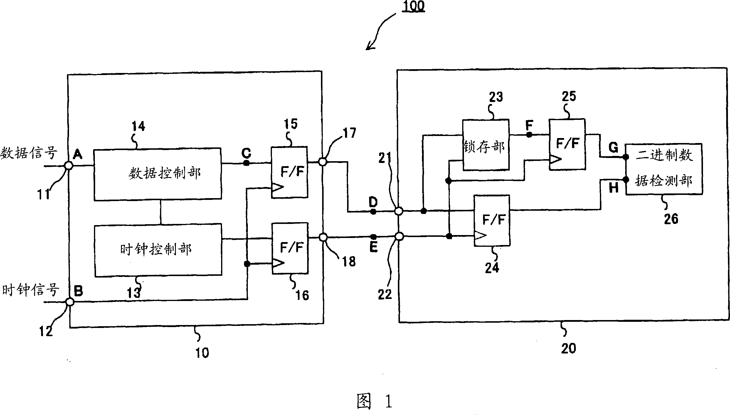
[0035] FIG. 1 is a block diagram showing the configuration of a data transfer system of the first embodiment. The data transmission system 100 of the first embodiment is a system for transmitting serial data. As shown in FIG. 1 , the system includes: a data sending unit 10 and a data receiving unit 20 . The data transmitting unit 10 transmits a serial data signal to the data receiving unit 20 . The data receiving unit 20 receives the serial data signal.

[0036] The data transmission unit 10 includes input terminals 11 , 12 , a clock control unit 13 , a data control unit 14 , flip-flops (hereinafter referred to as “F / F”) 15 , 16 , and output terminals 17 , 18 .

[0037] A data signal is input to the input terminal 11 . The data signal input through the input terminal 11 is input to the data control unit 14 . A clock signal is input to the input terminal 12 . The clock signal input through the input terminal 12 is input to F / F 15 , 16 .

[0038] The clock control section ...

no. 2 example

[0052] FIG. 4 is a block diagram showing the configuration of the data transfer system of the second embodiment. The data transfer system 200 of the second embodiment is a data processing device built in an LSI. The system includes: a high-speed processing unit 30 , a clock frequency dividing unit 40 , and a low-speed processing unit 50 . The data signal processed in the high-speed processing section 30 is sent to the low-speed processing section 50 . In the embodiment shown in FIG. 4, the data signal is depicted as a parallel format data signal. Alternatively, the data signal may be in serial format.

[0053] The high-speed processing unit 30 outputs a parallel data signal input from the outside based on a clock signal supplied from the outside. The high-speed processing section 30 includes FF31, the number of which is equal to the number of data widths of the parallel data signal.

[0054] The clock frequency dividing section 40 includes an FF 41 and an inverter 42 , and...


PUM


Abstract

The data transfer rate is enhanced without increasing the clock rate and the number of data signal lines, a data transfer system includes: a data transmitting section which transmits a second clock signal generated by frequency dividing a first clock signal, and a data signal including two bits for each cycle of the second clock signal; and a data receiving section which receives the second clock signal and the data signal, and which independently detects the two bits included in the data signal for each cycle of the second clock signal.

Description

technical field [0001] The present invention relates to a data transfer system and a data processing apparatus in which the data transfer rate is improved. Background technique [0002] With the spread of third-generation cellular phones and the increase in network speed, data such as image data, moving picture data, and program data are required to be processed at high speed. Accordingly, the operating clock rate of the LSI in the portable phone is increased, or the number of data signal lines is increased, thereby increasing the data processing speed and the data transfer rate. According to the technique disclosed in JP-A-2004-7797, high-speed transmission and low power consumption can be obtained. [0003] Patent Document 1: JP-A-2004-7797 [0004] However, when the operating clock rate is increased, the power consumption of the LSI increases. In battery-operated devices, such as mobile phones, an increase in power consumption leads to a decrease in operating time and ...

Claims


Application Information

Patent Timeline
Patent Type & Authority Applications(China)
IPC IPC(8): H04L25/38H04L25/40
CPCH04L7/02H04L25/4906H04L7/0008H04L7/0045H03K19/0175H04L25/02
Inventor 尾藤慎治
Owner PANASONIC CORP
Why Eureka
Try Eureka