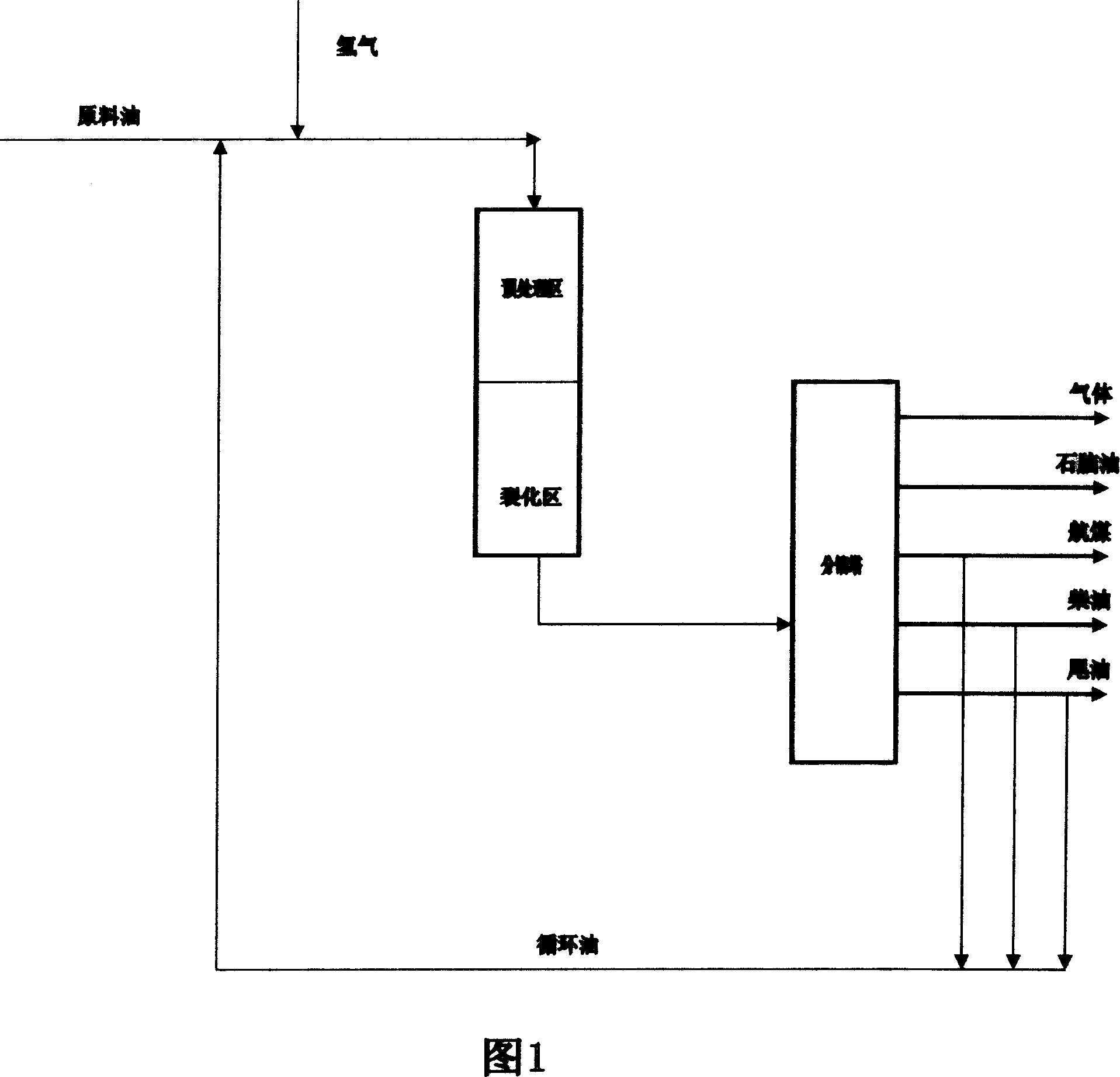
Single-stage hydrocracking process
A hydrocracking, single-stage technology, which is applied in the fields of hydrocarbon oil cracking and petroleum industry, etc., can solve the problems of shortening the service life of the catalyst, increasing the severity of the operation, reducing the processing capacity, etc., so as to reduce the construction investment and operation cost and increase the aromatics Saturation capacity, effect of enhancing hydrogenation performance
- Summary
- Abstract
- Description
- Claims
- Application Information
AI Technical Summary
Problems solved by technology
Method used
Image
Examples
Embodiment 1
[0037] Add 1000mL of water into the reaction tank, then add 40g of nickel chloride to dissolve, then add 52g of ammonium metatungstate to dissolve, then add 5g of zirconium oxychloride to dissolve, then add 10% ammonia water to form a gel until the pH value is 8, and then gel The temperature is 50°C, aging for 1 hour after forming the gel, and then filtering, adding 600ml of clean water, 16g of molybdenum trioxide and 32g of aluminum hydroxide to the filter cake, beating and stirring evenly, filtering, drying the filter cake at 80°C for 5 hours, and then extruding Molded, washed 3 times with clean water, dried at 120°C for 5 hours, and calcined at 500°C for 4 hours to obtain the final catalyst A. The composition and main properties are shown in Table 1.
Embodiment 2
[0039] According to the method of Example 1, according to the component content ratio of catalyst B in Table 1, add aluminum chloride, nickel chloride, sodium tungstate in the reaction tank, then add 16% ammonia water to form a gel, until the pH value is 9 , the gelling temperature is 80°C, aging for 3 hours after gelling, then filtering, washing the filter cake twice with 500mL clean water, adding clean water and molybdenum trioxide, beating and stirring evenly, filtering, and drying the filter cake at 70°C for 7 hours , and then extruded, washed twice with clean water, dried at 100°C for 8 hours, and calcined at 550°C for 3 hours to obtain the final catalyst B. The composition and main properties are shown in Table 1.
Embodiment 3
[0041]According to the method of Example 1, according to the component content ratio of catalyst C in Table 1, nickel nitrate, ammonium metatungstate, aluminum hydroxide, silica sol are added to the reaction tank, and then 12% ammonia water is added to form a gel until the pH The value is 10, the gelling temperature is 60°C, aging for 2 hours after gelling, then filtering, adding molybdenum trioxide to the filter cake, beating and stirring evenly, filtering, drying the filter cake at 120°C for 1 hour, and then extruding into strips, wet strips It was dried at 130°C for 3 hours and calcined at 600°C for 3 hours to obtain the final catalyst C, whose composition and main properties are shown in Table 1.
PUM
 Abstract
Description
Claims
Application Information
 - R&D
- Intellectual Property
- Life Sciences
- Materials
- Tech Scout
- Unparalleled Data Quality
- Higher Quality Content
- 60% Fewer Hallucinations
Browse by: Latest US Patents, China's latest patents, Technical Efficacy Thesaurus, Application Domain, Technology Topic, Popular Technical Reports.
© 2025 PatSnap. All rights reserved.Legal|Privacy policy|Modern Slavery Act Transparency Statement|Sitemap|About US| Contact US: help@patsnap.com

