Control valve of brake

A technology for controlling valves and brakes, which is applied in the direction of brakes, control valves, air release valves, and brake components. Internal leakage, easy assembly and production

Inactive Publication Date: 2007-12-26
YUZHOU HYDRAULIC EQUIP FACTORY
View PDF1 Cites 16 Cited by
  • Summary
  • Abstract
  • Description
  • Claims
  • Application Information

AI Technical Summary

Problems solved by technology

[0002] At present, the control of hydraulic brakes of winches or hoists in domestic construction machinery equipment is basically controlled by system pressure, as shown in Figure 1 and 2. Due to the influence of system back pressure, the braking force is weakened when the system is in the middle position, especially the engine in the middle position of the system. When the speed is high, the back pressure of the system increases, causing the brake of the winch or winch to open and the heavy object to slide down, and because the high pressure of the system is 25-28Mpa, it is easy to cause oil leakage from the brake piston. As the pressure level of the hydraulic system of construction machinery gradually increases, The brake pressure of the winch or winch is generally less than 20Mpa, and a new brake control valve needs to be designed to solve this technical problem
[0003] The Chinese patent No. 01244459.6 is "Crane Back Pressure Compensated Brake Control Valve". The bottom surface of the body is vertically connected with two cartridge shuttle valves. Since the back pressure compensating brake control valve is used to eliminate the phenomenon of brake out of control caused by the back pressure of the system, the high pressure brake is changed to low pressure brake, which avoids the brake due to high pressure. Oil leakage and oil seepage certainly have the progressive significance as described, but because two sets of hydraulically controlled reversing valves, shuttle valves and a pressure reducing valve are used, the structure is bound to be complicated, and the volume of the valve body is not easy to reduce. The cost is relatively high and needs further improvement

Method used


Image

  • Control valve of brake
  • Control valve of brake
  • Control valve of brake

Examples


Embodiment Construction

[0014] The present invention will be further described in detail below in conjunction with the accompanying drawings and embodiments.

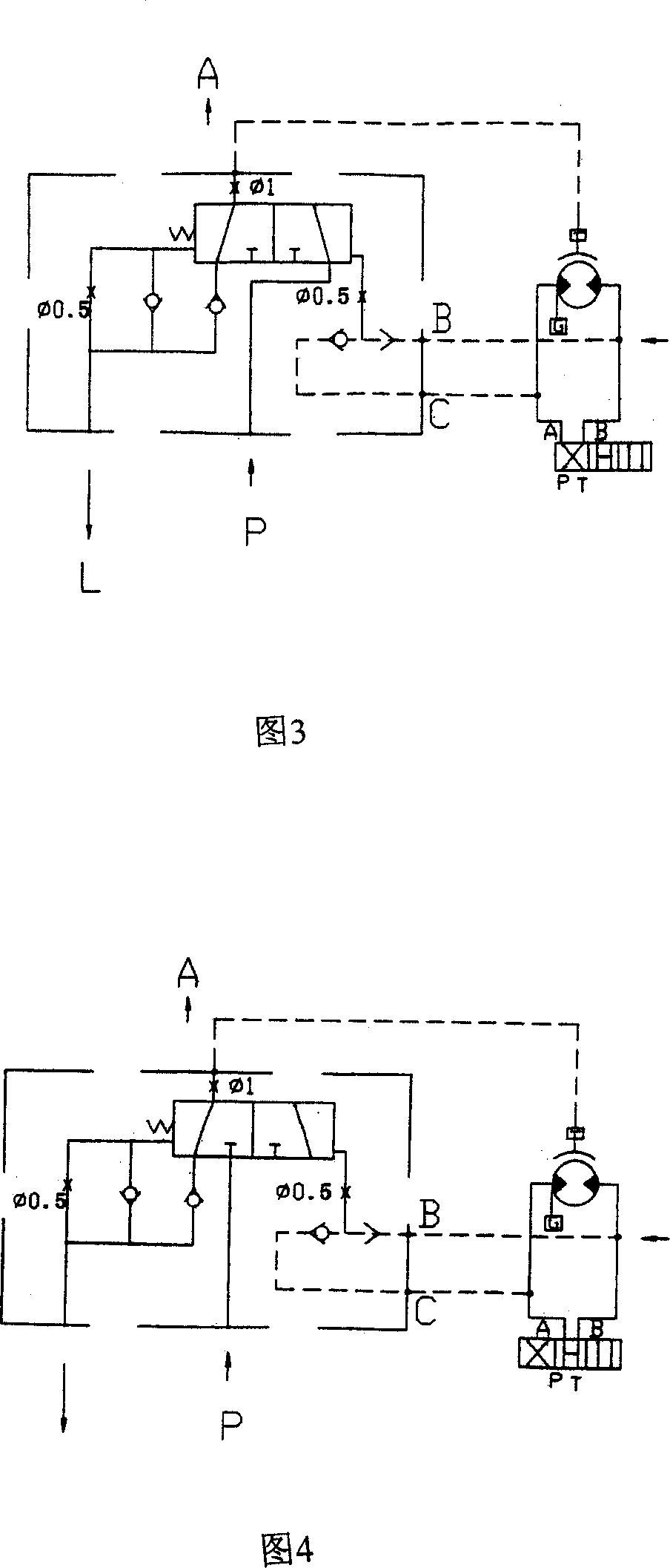
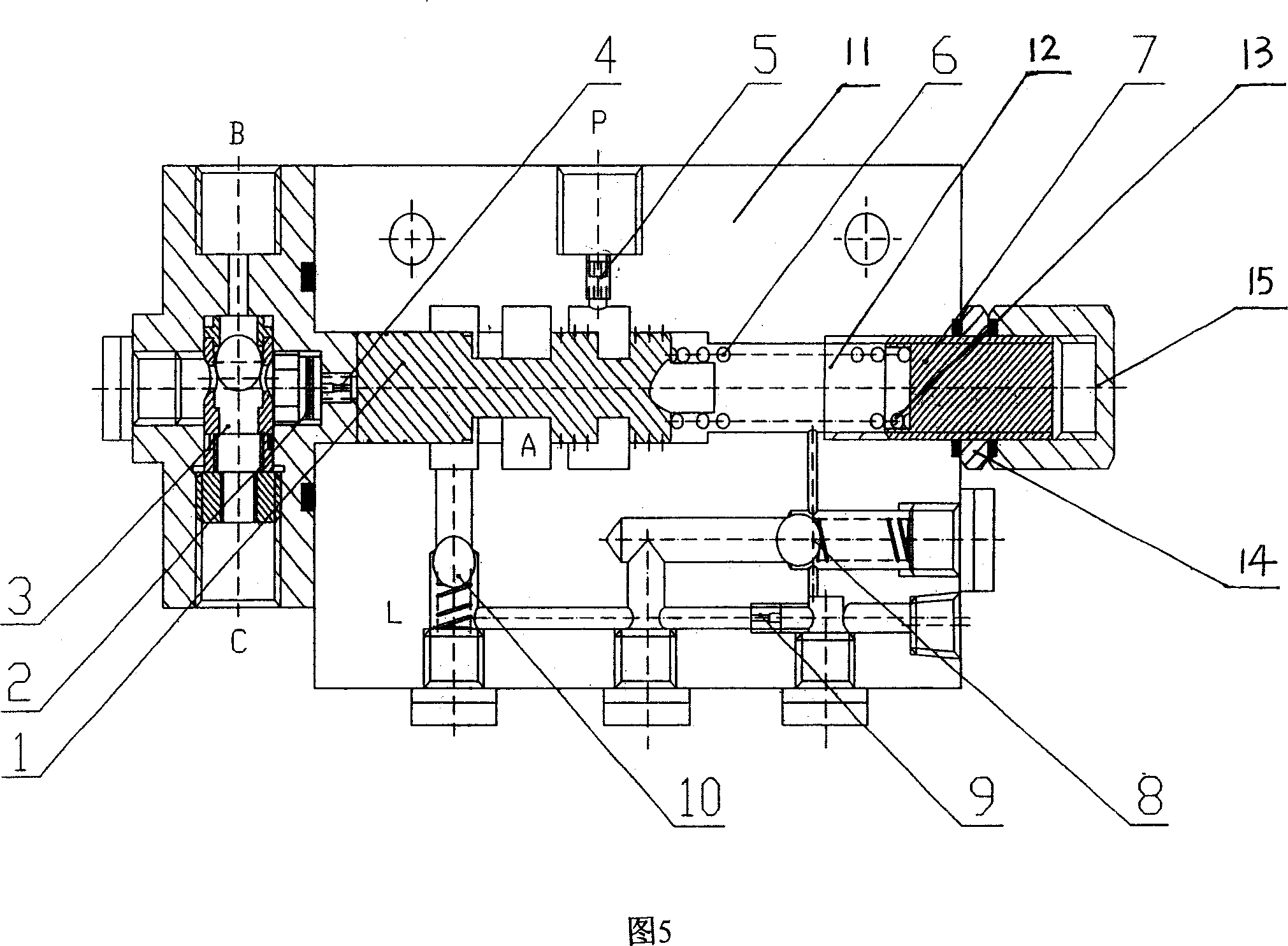
[0015] As shown in Figure 3-5, the control valve of this kind of brake includes a valve body 11, a valve core 1 and a shuttle valve 3 installed in the valve body 11, wherein the valve core 1 is a two-position three-way valve core , one end of the spool 1 is connected to the output end of the shuttle valve 3 through the damping 4 at the input end of the system, and the two input ends of the shuttle valve 3, namely the control valve interface B and interface C, are respectively connected to the pressure output end of the hydraulic system. The spring chamber 12 at the other end is connected to the oil tank through the parallel valve core motion counterbalance damper 9 and the oil supply check valve 8, the input port P of the control valve is connected to a low-pressure constant pressure source, and the valve core cavity is connected to the control...


PUM


Abstract

The invention relates to control valve of braking device that includes valve body, valve core and shuttle valve. The feature is that the valve core adopts two position and tee coupling valve core. One end of valve core connects to the output end of shuttle valve. The input end of shuttle interface B and C connect to hydraulic system pressure output end. The other end of spring cavity of valve core connects to oil tank. And the input interface of control valve P connects to low voltage constant pressure resource. The cavity of valve core connects to output interface A of control valve through output end. The output interface A connects to brake. Cavity of valve core connects to interface L, which connects to oil tank, through return check valve and control valve. The invention has the advantages of simple and small volume, etc.

Description

technical field [0001] The invention relates to a control valve for a brake. Background technique [0002] At present, the control of hydraulic brakes of winches or hoists in domestic construction machinery equipment is basically controlled by system pressure, as shown in Figure 1 and 2. Due to the influence of system back pressure, the braking force is weakened when the system is in the middle position, especially the engine in the middle position of the system. When the speed is high, the back pressure of the system increases, causing the brake of the winch or winch to open and the heavy object to slide down, and because the high pressure of the system is 25-28Mpa, it is easy to cause oil leakage from the brake piston. As the pressure level of the hydraulic system of construction machinery gradually increases, And winch or winch brake pressure resistance is generally all less than 20Mpa, also need to design new brake control valve to solve this technical problem. [0003]...

Claims


Application Information

Patent Timeline
Patent Type & Authority Applications(China)
IPC IPC(8): B60T15/06B66C13/18
Inventor 卢永松李新
Owner YUZHOU HYDRAULIC EQUIP FACTORY
Why Eureka
Try Eureka