
Exhaust gas receiver for a large two-stroke diesel engine

A diesel engine, exhaust gas collection technology, applied to engine components, machines/engines, exhaust gas treatment, etc.

Active Publication Date: 2010-09-01
曼能解决方案(曼能解决方案德国股份公司)分公司
View PDF4 Cites 0 Cited by
  • Summary
  • Abstract
  • Description
  • Claims
  • Application Information

AI Technical Summary

Problems solved by technology

This means that the cylinders adjacent to the turbocharger are not operating at optimum efficiency, thus reducing overall engine performance

Method used


Image

  • Exhaust gas receiver for a large two-stroke diesel engine
  • Exhaust gas receiver for a large two-stroke diesel engine
  • Exhaust gas receiver for a large two-stroke diesel engine

Examples


Embodiment Construction

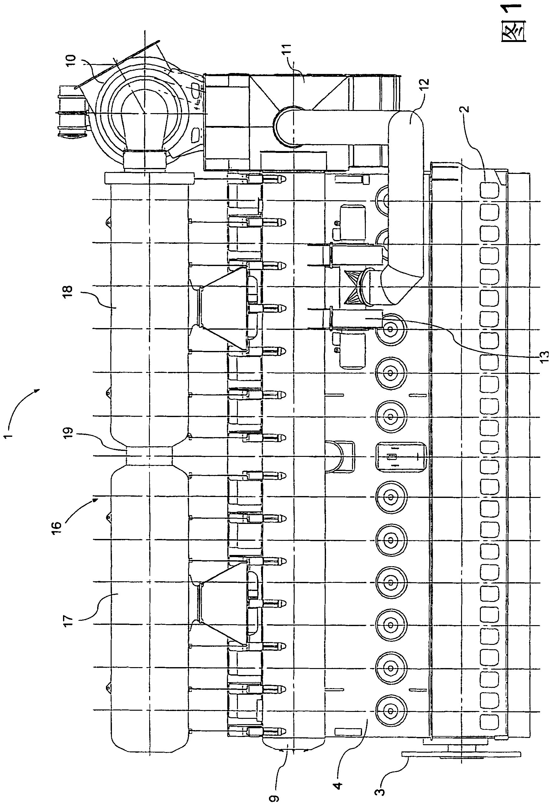
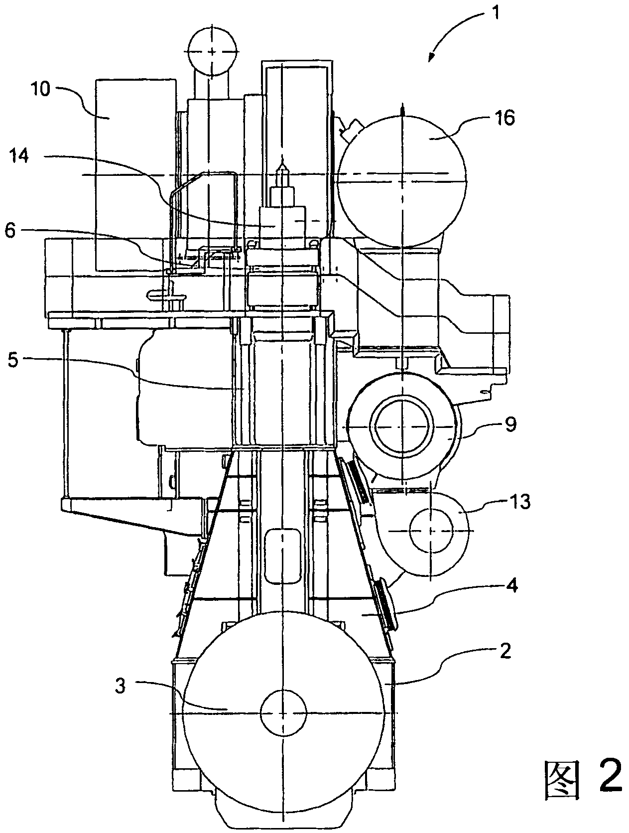
[0034] figure 1 and figure 2 A side view and a rear view of an engine 1 according to a preferred embodiment of the invention are shown respectively. The engine 1 is a crosshead type unidirectional flow low-speed two-stroke crosshead diesel engine, which can be a propulsion system in a ship or a prime mover in a power station. These engines typically have 3 to 14 cylinders in-line. The engine 1 is formed on a base plate 2 with main bearings for the crankshaft (only the flywheel 3 attached to the end of the crankshaft can be seen).

[0035] Depending on the manufacturing equipment, the base plate 2 can be made in one piece or divided into several parts of appropriate size.

[0036] An A-frame box 4 of welded design is mounted on the base plate 2 . On the exhaust side, the frame box 4 is provided with safety valves for the individual cylinders, while on the camshaft side the frame box 4 is provided with large hinged doors for the individual cylinders. The crosshead guide s...


PUM


Abstract

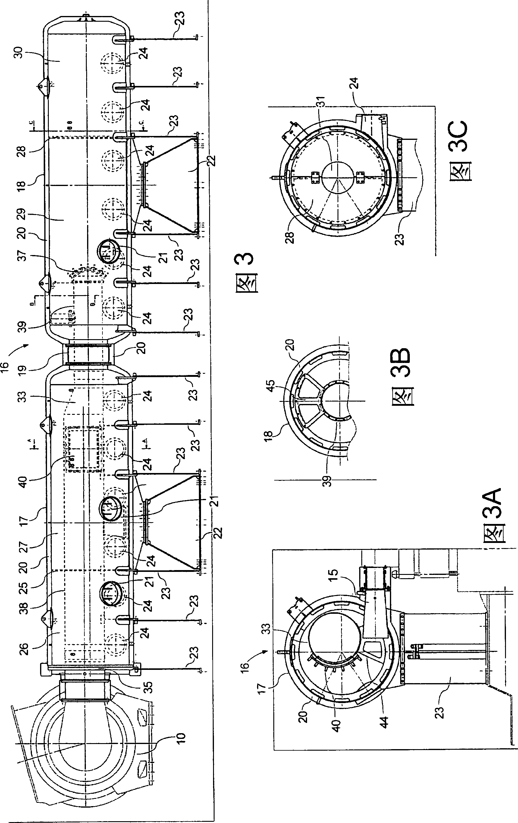
The invention discloses a long exhaust gas receiver for a large two-stroke diesel engine with a plurality of cylinders. The exhaust gas receiver is divided into several chambers longitudinally and is positioned with some exhaust gas inlet distributed along the length thereof. One of the longitudinal ends of the exhaust gas reservoir is positioned with an outlet. A pressure distribution pipe is positioned in the exhaust gas receiver and connected to the chamber far away from the outlet and provided with a lateral opening which connects the inside of the inside of the pressure distribution pipeto the chamber more close to the outlet.

Description

technical field [0001] The invention relates to an exhaust gas collector for a large two-stroke diesel engine, in particular to an exhaust gas collector for an in-line engine with multiple cylinders. Background technique [0002] Exhaust collectors of large two-stroke diesel engines are highly loaded components that receive hot (450° C.) exhaust gases from the cylinders at a pressure of about 4 bar each. At the extremes of thermal and pressure loads, the vibrations of the engine shake the structure, further increasing the mechanical loads on the exhaust collector. Due to the large size of the exhaust collector (the length can be well over 10 meters) and the high operating temperature, the thermal expansion of the exhaust collector is very significant, and large engines have to be divided into two or more housing parts by bellows to absorb the Exhaust collectors for dimensional changes caused by thermal expansion. The entire exhaust gas collector and any associated componen...

Claims


Application Information

Patent Timeline
Patent Type & Authority Patents(China)
IPC IPC(8): F01N7/08F01N13/10
CPCF01N13/08F01N13/1838F01N2260/06F01N2260/14
Inventor 克劳斯·内克索·尼尔森
Owner 曼能解决方案(曼能解决方案德国股份公司)分公司
Learn More