Automatic control turbine synchronous discharging-suction pump

A technology of suction pump and pump body, which is applied in the field of self-controlled turbine synchronous suction pump, which can solve the problems of large floor area, easy corrosion and leakage of bottom valve, long exhaust time, etc., to save investment, land occupation, and energy saving The effect is obvious and the suction loss is small

Inactive Publication Date: 2008-01-09
SHENYANG ANTI CORROSION ALLOY PUMP
View PDF0 Cites 6 Cited by
  • Summary
  • Abstract
  • Description
  • Claims
  • Application Information

AI Technical Summary

Problems solved by technology

[0003] 1. Ordinary centrifugal pumps are equipped with water ring or rotary vane vacuum pumps: to create vacuum conditions for the pump system, so that the medium enters the pump system under atmospheric pressure and then starts the pump to drain water. The disadvantage of this method is that the vacuum pump exhausts for a long time and the equipment is used. Low service life, high failure rate, not suitable for special working conditions of acid, alkali, salt chemical products, etc.
[0004] 2. Self-priming pump: Its working principle is to use the pre-stored medium in the pump chamber under the action of the pump to wrap and discharge the air in the suction pipe during the internal circulation process before it can operate normally. The disadvantage is the exhaust time long and inefficient
[0005] 3. Building a low-level pump room or a high-level liquid storage tank: to make an inlet pressure head for the pump. The disadvantages are that the infrastructure investment is large, the area is large, and the maintenance of the equipment is difficult. The above several technological measures have the existence of equipment that must be kept warm in winter. The problem
[0006] 4. The bottom valve is installed at the suction port of the pump: after the pump is filled with water before running, it starts to run. The disadvantage is that the bottom valve is easy to corrode and leak, so it must be replaced frequently

Method used


Image

  • Automatic control turbine synchronous discharging-suction pump
  • Automatic control turbine synchronous discharging-suction pump
  • Automatic control turbine synchronous discharging-suction pump

Examples


Embodiment 1

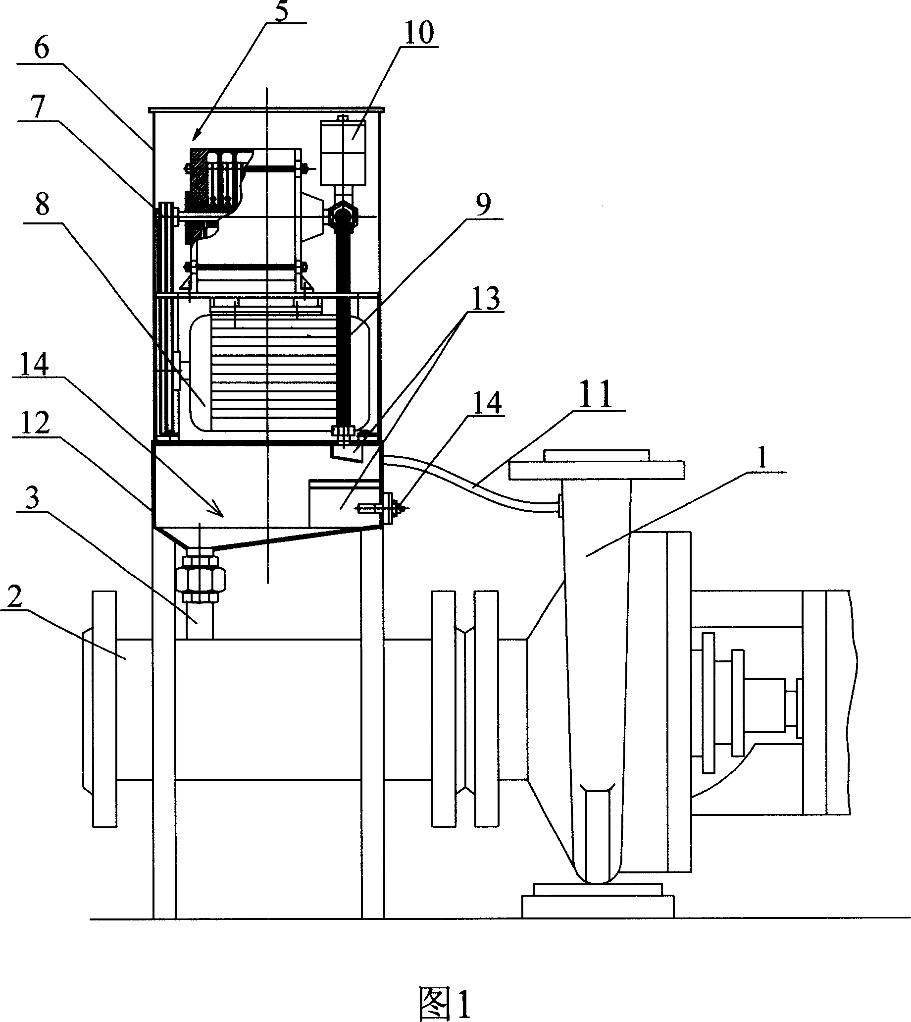
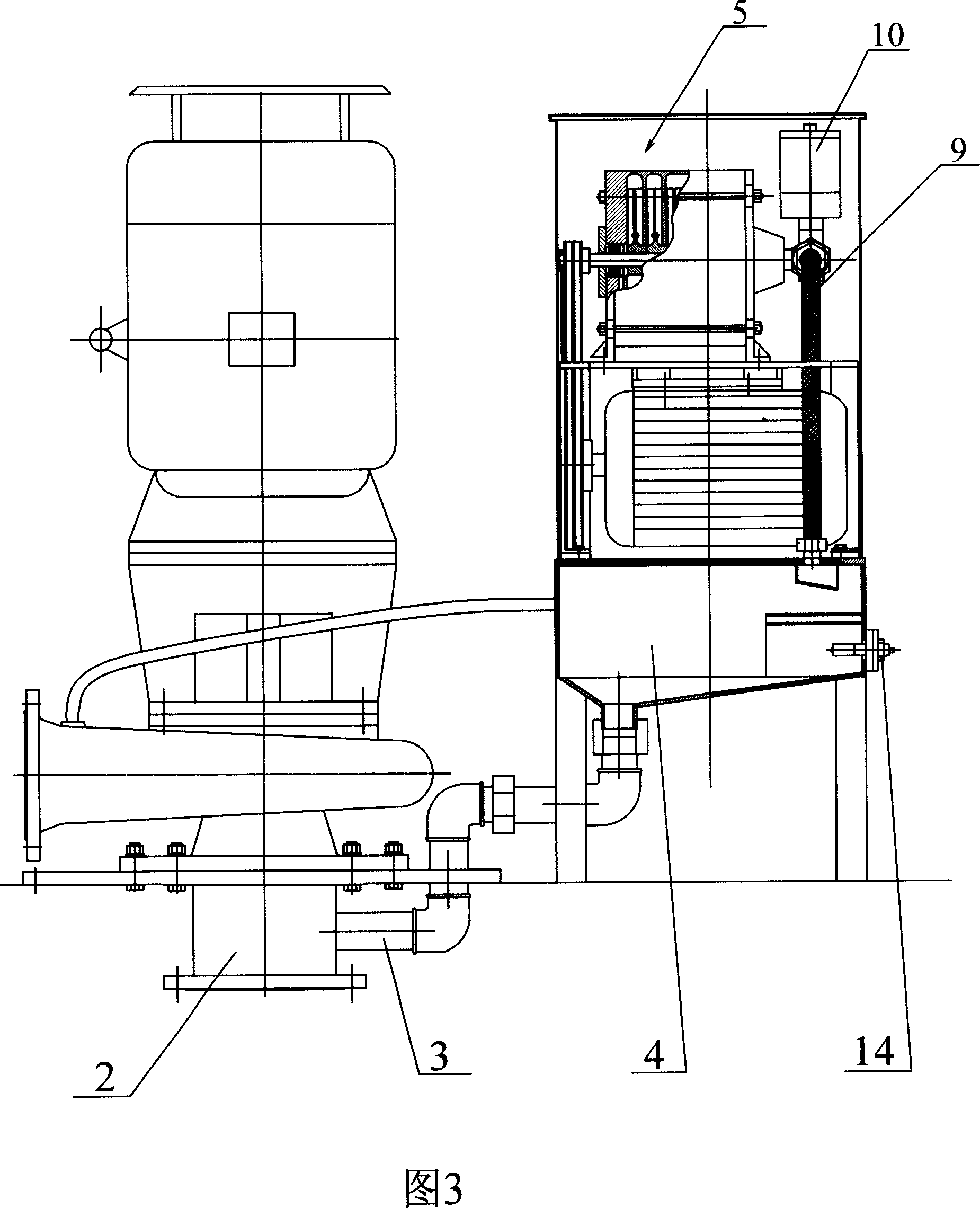
[0034] The self-controlled turbine synchronous exhaust-suction pump includes a delivery pump 1 and a suction connection 2, the rear end of the suction connection 2 is airtightly connected to the suction port of the delivery pump 1, and the gas-liquid separator 4 is arranged on a negative pressure device 5 . There is an air suction port at the bottom of the gas-liquid separator 4, and the air suction port is connected with the suction connecting pipe 2 through a suction pipe 3, and communicated with each other. A pressure balance pipe 11 is connected between the gas-liquid separator 4 and the inner cavity of the delivery pump 1 . The negative pressure device 5 includes a vacuum blower 7 and a motor 8 in which the casing 6 is arranged. The vacuum fan 7 adopts a single-stage centrifugal fan, and the conveying pump 1 is a vane type. There is a connecting pipe 9 between the negative pressure device 5 and the gas-liquid separator 4, and a vacuum solenoid valve 10 is installed on th...

Embodiment 2

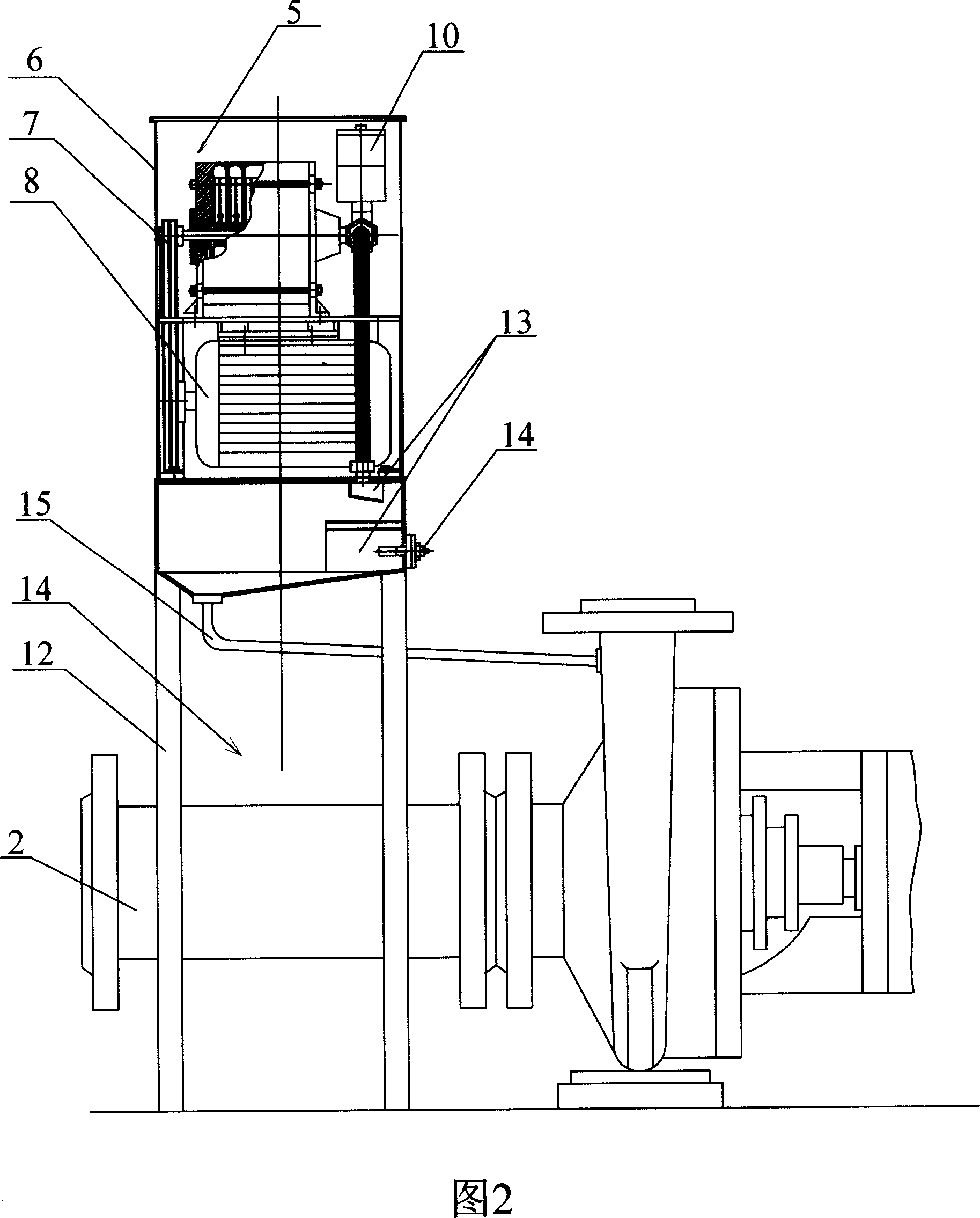
[0036] Embodiment two is basically the same as embodiment one, and its difference is that the suction port at the bottom of the gas-liquid separator 4 communicates with the exhaust port on the delivery pump 1 through a connecting pipe 15, and the bottom of the gas-liquid separator 4 The suction port is higher than the exhaust port on the top of the transfer pump 1 .


PUM


Abstract

This invention is self-controlling turbine synchronous discharging and absorbing pump. It includes pump body and absorb connecting pipe. The air outlet opening, which communicates to pump body internal cavity, is arranged on the upper part of pump body. The air outlet opening discharges air through a negative pressure device. The negative pressure device has a gas liquid separator, on which has at least one liquid level sensor. The bottom of the said gas liquid separator has one air absorbing opening. This invention has no etching and has long operational life span. It does not need the bottom valve and has high efficiency. This invention starts with high liquid level and stops with low liquid level. It also has intelligent machine stopping protection device. When the medium is empty, the machine stops automatically. It can control remotely. This invention can be assembled vertically and horizontally. It can be moved or fixed.

Description

(1) Technical field [0001] The invention relates to a pump, in particular to a pump combined with a conveying pump and a negative pressure device. (2) Background technology [0002] Pumps are one of the main equipment for conveying liquid media, widely used in petroleum, chemical industry, electric power, urban construction, environmental protection, sewage treatment, food, pharmaceuticals, synthetic fibers, mining, papermaking, construction, metallurgy, fire protection, tap water, ships and tank cars Unloading and other industrial sectors. At present, the process measures widely used in the working condition of pump suction and discharge of low-level medium are as follows: [0003] 1. Ordinary centrifugal pumps are equipped with water ring or rotary vane vacuum pumps: to create vacuum conditions for the pump system, so that the medium enters the pump system under atmospheric pressure and then starts the pump to drain water. The disadvantage of this method is that the vacuu...

Claims


Application Information

Patent Timeline
Patent Type & Authority Applications(China)
IPC IPC(8): F04D9/02
Inventor 韩杰
Owner SHENYANG ANTI CORROSION ALLOY PUMP
Why Eureka
Try Eureka