Underwater sound communications and alarming method and device
An alarm device, underwater sound technology, applied in signal transmission systems, non-electrical signal transmission systems, instruments, etc., can solve the problems of inability to work, large size, lack of safety means for passengers, etc., and achieve simple circuits and easy miniaturization. Effect
- Summary
- Abstract
- Description
- Claims
- Application Information
AI Technical Summary
Problems solved by technology
Method used
Image

Examples
Embodiment Construction
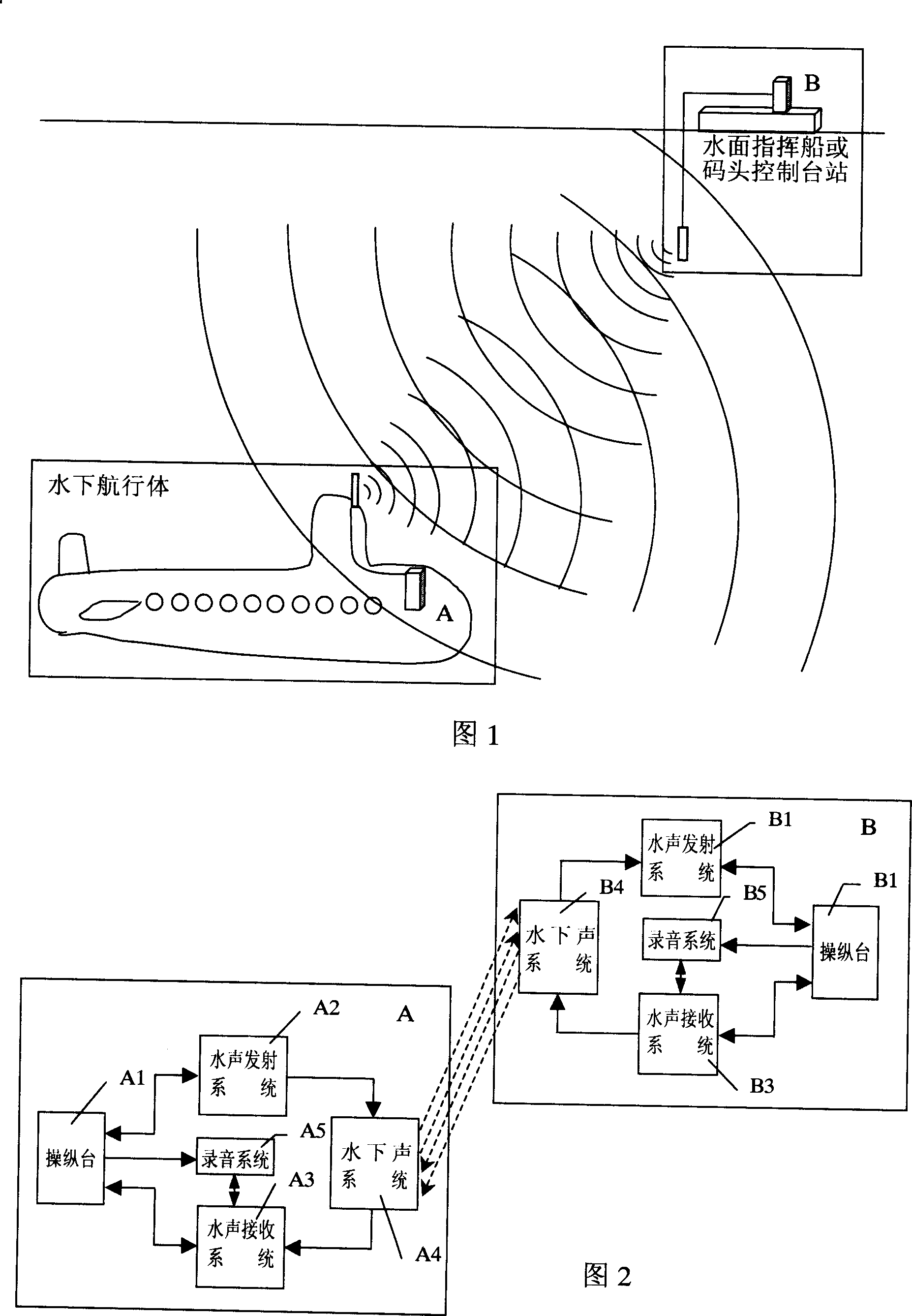
[0089] Fig. 1 and Fig. 2 show the principle schematic diagram of the underwater acoustic communication and alarm method and device configuration of the present invention. The water system navigation body and the surface command ship or dock control station must be equipped with underwater acoustic communication and alarm devices A and B using the same communication and alarm system and using water as the transmission medium. The underwater acoustic emission system A2 of device A transmits via the carrier frequency The modulated voice or telegraph or dual-frequency alarm coded signal is converted into an underwater acoustic carrier frequency signal through the underwater acoustic system A4 for electro-acoustic energy, transmitted through the water medium, and reaches the underwater acoustic system B4 of the device B for acoustic-electric conversion. The energy is converted into a carrier frequency electrical signal, sent to the underwater acoustic receiving system B3, and the re...
PUM
 Abstract
Description
Claims
Application Information