Method and apparatus for producing three-dimensional structure

A technology of three-dimensional structure and manufacturing method, which is applied in the direction of microstructure devices, manufacturing microstructure devices, microelectronic microstructure devices, etc., and can solve problems such as inapplicable, difficult to realize, and incapable of three-dimensional stacking

Active Publication Date: 2008-01-23
PANASONIC CORP
View PDF4 Cites 22 Cited by
  • Summary
  • Abstract
  • Description
  • Claims
  • Application Information

AI Technical Summary

Problems solved by technology

[0009] As mentioned above, the conventional nanoimprinting technology is sometimes not suitable for high-variety low-volume production or trial production of devices with many design changes because many micro-molds are required.
Moreover, the manufacture of micro-molds is often difficult to achieve
[0010] On the other hand, the conventional inkjet printing technology is a technology that can flexibly respond to design changes and can form a two-dimensional shape in a short time. However, the problem is that the material that can be ejected from the nozzle is limited to a low Viscosity of the material
However, low-viscosity materials diffuse laterally on the substrate, so they cannot be stacked in three dimensions. Therefore, it is difficult to manufacture three-dimensional structures with the conventional inkjet printing technology.

Method used


Image

  • Method and apparatus for producing three-dimensional structure
  • Method and apparatus for producing three-dimensional structure
  • Method and apparatus for producing three-dimensional structure

Examples


Embodiment approach 1

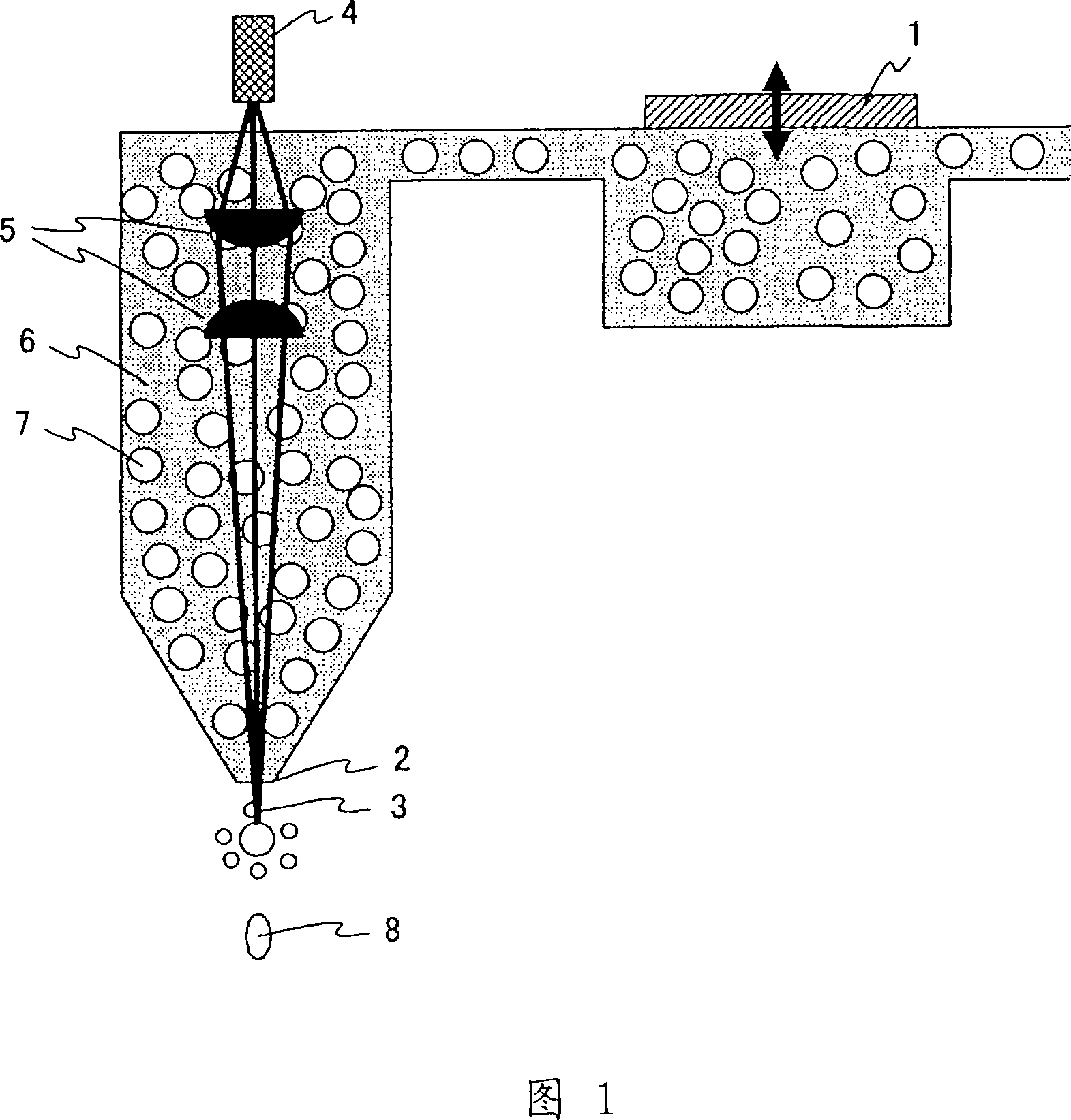
[0078] FIG. 1 shows an example of an inkjet head, which is a part of an apparatus for manufacturing a three-dimensional structure. 1 denotes a piezoelectric element, 2 denotes a nozzle, 3 denotes a laser, 4 denotes a laser, 5 denotes a lens, 6 denotes a solvent, 7 denotes a polymer particle, and 8 denotes a liquid droplet whose viscosity has been increased.

[0079] The piezoelectric element 1 is vibrated at a high speed, and the solvent 6 and the polymer particles 7 are ejected from the nozzle 2 as droplets. Laser light 3 is oscillated from laser 4 (for example, YAG laser, semiconductor laser, or ultraviolet laser, etc.), and laser light 3 is converted into parallel light by lens 5, and then, the focal point of laser light 3 that has been converted into parallel light is focused on the nozzle. on the droplet.

[0080]Using a focused laser light, the ejected droplets are heated to evaporate the solvent and melt the polymer particles contained in the solution. As a result, th...

Embodiment approach 2

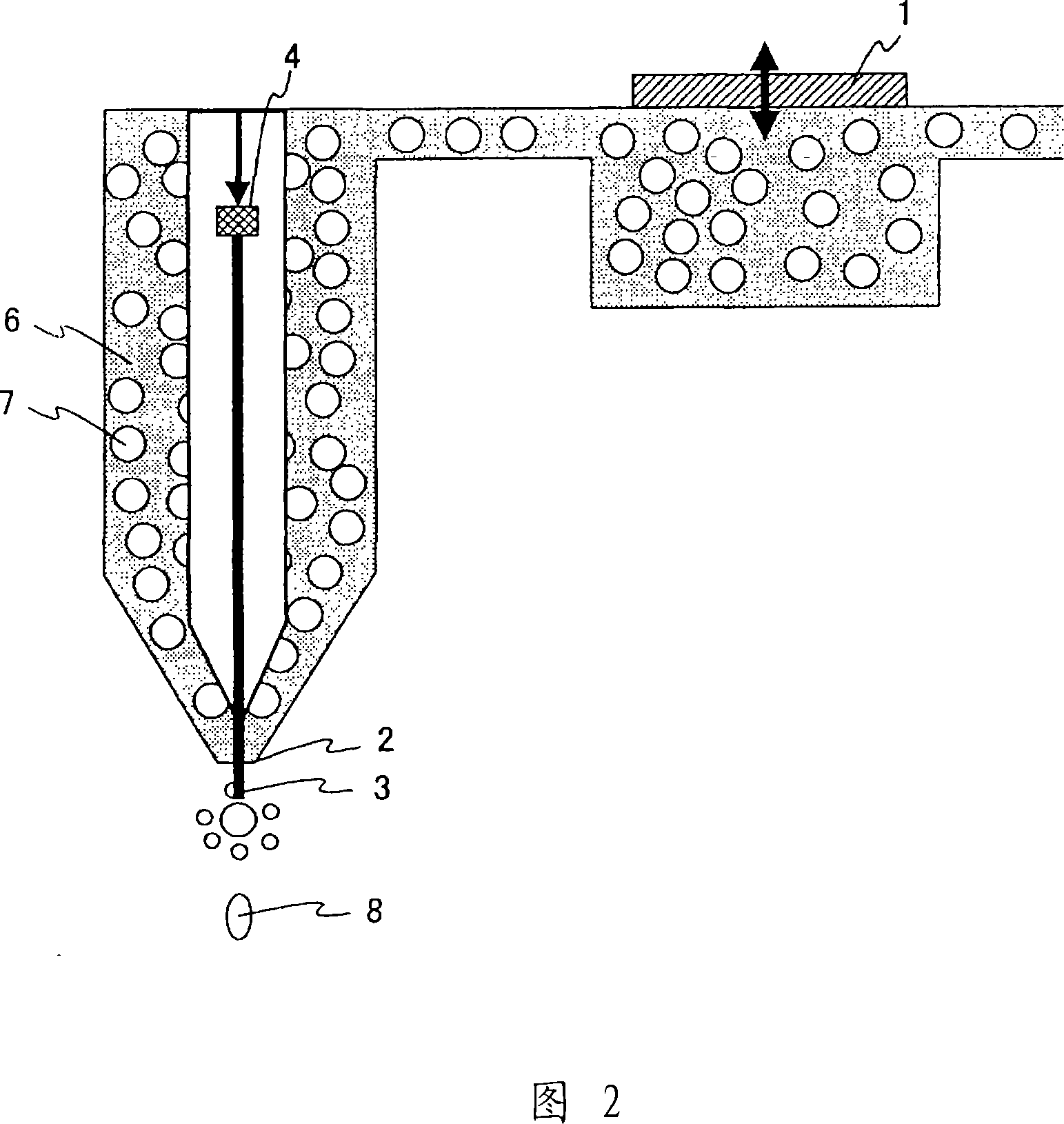
[0084] FIG. 2 shows another example of an inkjet head, which is a part of the apparatus for manufacturing a three-dimensional structure. In FIG. 2 , the same reference numerals are used for the same components as those in FIG. 1 , and explanations thereof are omitted.

[0085] The liquid droplets of the solution containing the polymer particles 7 are ejected by vibrating the piezoelectric element 1 provided in the inkjet head at high speed. The laser 4 is provided in a cylinder provided at a central position inside the inkjet head. Also, keep the solution from flowing into the cylinder.

[0086] In order to facilitate the ejection of the solution, gas may also flow out from a cylinder provided inside the inkjet head. The gas, which can be hot air, is used to change the viscosity of the sprayed liquid droplets.

[0087] When the laser 3 is irradiated on the ejected liquid droplets, the solvent (such as water) evaporates, and the polymer particles contained in the liquid drop...

Embodiment approach 3

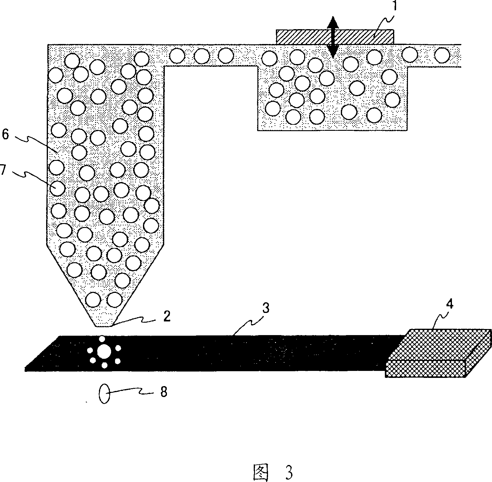
[0090] 3 and 4 show another example of an inkjet head, which is an apparatus for manufacturing a three-dimensional structure in the present invention. In FIGS. 3 and 4 , the same reference numerals are used for the same constituent elements as those in FIG. 1 , and description thereof will be omitted.

[0091] By vibrating the piezoelectric element 1 inside the inkjet device at high speed, droplets of the solution containing the polymer particles 7 can be ejected. The laser 4 is arranged outside the inkjet head. In FIG. 3 , it is arranged at a position substantially horizontal to the nozzle; in FIG. 4 , it is arranged at an oblique upper part of the nozzle. As shown in the figure, if the laser beam 3 has a planar shape, it is relatively easy to irradiate the ejected polymer particles.

[0092] At this time, it is also possible to condense the laser light and irradiate the liquid droplets containing the polymer particles from the side. When the ejected liquid droplets are irr...


PUM

PropertyMeasurementUnit
particle sizeaaaaaaaaaa
boiling pointaaaaaaaaaa

Abstract

The present invention aims to produce a three-dimensional structure having a high aspect ratio by using inkjet printing techniques or the like. Specifically, a three-dimensional structure is produced by ejecting a liquid drop of a solution, which contains a solvent and polymer particles dispersed in the solvent while having a viscosity of not more than 100 cps, from a nozzle onto a substrate; then evaporating the solvent and melting the polymer particles by irradiating the liquid drop with light; and then depositing the molten polymer particles on the substrate. The present invention can be applied to production of biochips and the like.

Description

technical field [0001] The present invention relates to methods and devices for manufacturing three-dimensional structures. The present invention is characterized in that liquid droplets containing polymer particles are ejected using an inkjet printing technique or the like having a light irradiation mechanism. Background technique [0002] In recent years, people have researched and developed DNA chips or immunoassay chips for the purpose of separating and detecting various components including glucose in blood, or for separating DNA (Deoxyribonucleic acid, deoxyribonucleic acid) components. biosensors. In these devices, pillars are formed with diameters ranging from nanometers to micrometers and heights of several hundred micrometers. Therefore, in the fabrication process of devices, techniques for forming three-dimensional structures (including nano-pillars or micro-pillars) with higher aspect ratios are essential. [0003] In the past, in order to form a three-dimensi...

Claims


Application Information

Patent Timeline
Patent Type & Authority Applications(China)
IPC IPC(8): B29C67/00B05C5/00B05C9/12B05D1/26B05D3/02B81C5/00B81C99/00
CPCB01L3/502707B82Y30/00B41M7/0081B41M7/00B01J2219/00585B41M7/009B81B2203/0361B01J19/0046H05K2203/013B81C1/0046B01J2219/00527B41M7/0072H05K3/0079B01J2219/00596B01J2219/00378B81C99/0095B41M3/006B01J2219/00644B29C67/0059B01J2219/00711B29C64/112B29C67/00B81C99/00B05C5/00B05C9/12
Inventor 永井久雄吉田英博古川贵之井上隆史
Owner PANASONIC CORP
Why Eureka
Try Eureka