
Disc carrier for friction clutch

A friction clutch and disc technology, applied in the friction clutch field, can solve the problems of high cost, high tool cost, time-consuming, etc., and achieve the effects of reduced manufacturing cost, cost saving and low cost

Inactive Publication Date: 2008-01-30
赫尔比格驱动技术有限公司
View PDF0 Cites 2 Cited by
  • Summary
  • Abstract
  • Description
  • Claims
  • Application Information

AI Technical Summary

Problems solved by technology

However, these methods require the use of costly and time-consuming tooling to shape
When the mold is changed, due to design changes, for example, the diameter becomes smaller or larger, or the overall length becomes smaller or larger, which leads to high tooling costs

Method used


Image

  • Disc carrier for friction clutch

Examples


Embodiment Construction

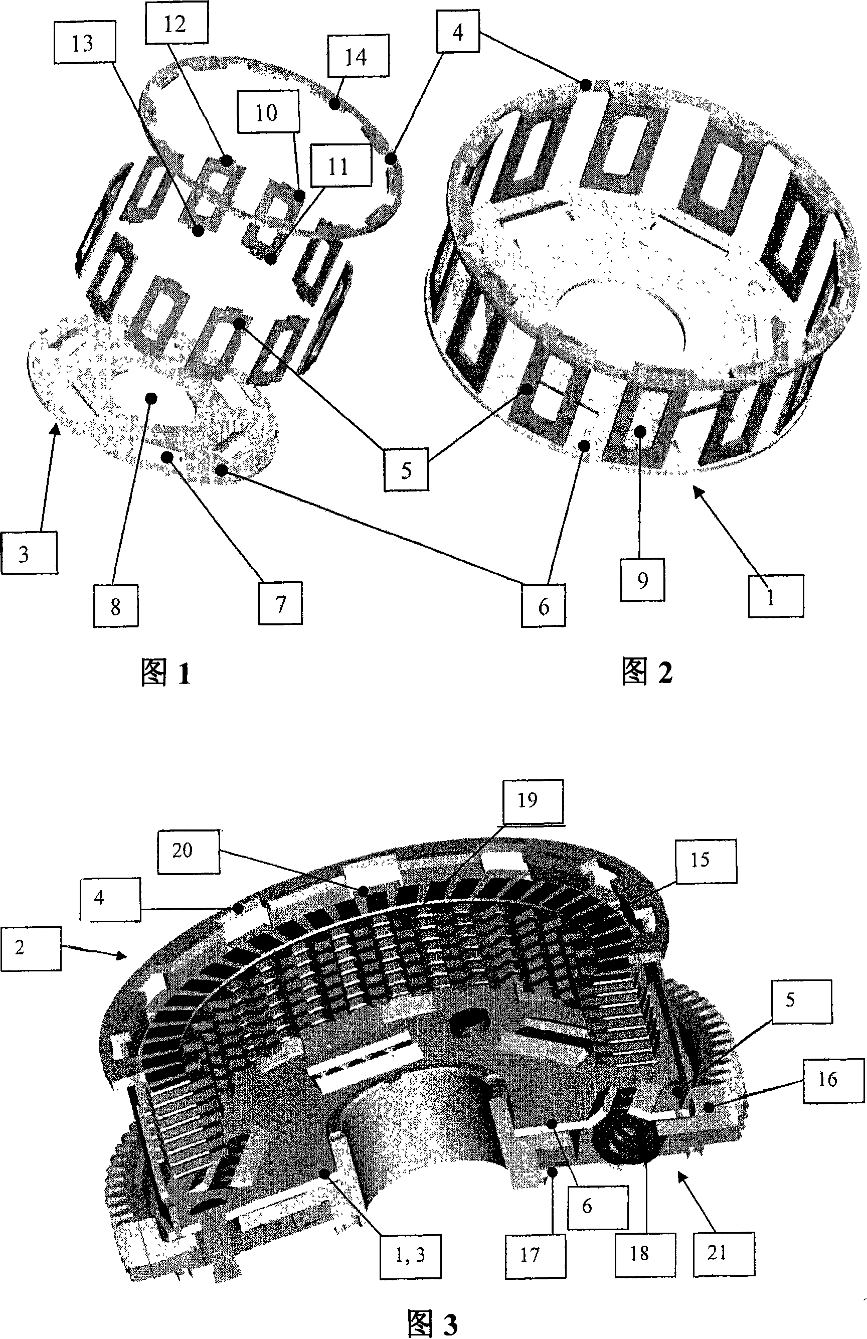
[0044] From the analysis of FIGS. 1 and 2 , the structure of the disc carrier 1 and its modular modular assembly 3 (shown in FIG. 1 ) of the present invention will become clear. According to FIG. 1 , the standard assembly 3 comprises, in the example, a circular retaining ring 4 and a base plate 6 . As shown in Figure 1, in the example, a plurality of webs (webs) are arranged between the elements 4 and 5, all of which have the same structure, two webs are indicated with reference numeral 5 in Figure 1 shape. In the example, twelve meshes are used, each constructed in the form of a frame and a rectangle with a rectangular central depression 9, as detailed in FIG. 1 .

[0045] Tabs 12 and 13 are arranged on the respective narrow sides 10 and 11 of the web 5, in the illustrated embodiment the web 5 with the tabs forming a flat plate member. The protrusions 12 and 13 are used to fix the mesh to the retaining ring 4 and the base plate 6 respectively.

[0046] The retaining ring 4...


PUM


Abstract

The present invention relates to a disc support (1) of the friction clutch (2), wherein, the modular-structured component (3) is composed of a plurality of elements (4, 5, 6) which are mutually connected.

Description

technical field [0001] The invention relates to a disc carrier for a friction clutch according to claim 1 and to a friction clutch according to the preamble of claim 11 . Background technique [0002] As the models of automobile manufacturers in the world automobile market are diversifying, it is necessary to gradually reduce the number of components of individual models. In addition, due to the frequent revision of models, models with a short life cycle are required. The design of the components of a vehicle's (car and / or motorcycle) drivetrain changes frequently due to the need to transmit greater torque or the need to reduce weight. [0003] For the friction clutch of the vehicle transmission system, the housing of the existing clutch system is manufactured by steel forming process, casting process or light metal mold casting process, etc. as known in the market. However, these methods require the use of costly and time-consuming tooling for shaping. This leads to high...

Claims


Application Information

Patent Timeline
IPC IPC(8): F16D13/68
CPCF16D13/683Y10T74/213F16D69/04F16D13/64F16F15/123
Inventor 艾哈迈德·沙希欧尼福克·尼克尔乔治·鲁普雷希特
Owner 赫尔比格驱动技术有限公司
Learn More