
Impregnation forming method for capacitor core assembly

A technology of impregnation molding and capacitors, which is applied in capacitors, capacitor manufacturing, circuits, etc., can solve problems such as high viscosity of liquids, difficult penetration of core groups, aging failures, etc., and achieve the reduction of liquid surface tension, stable feeding speed, and stable quality Effect

Active Publication Date: 2008-02-13
CHENGDU HONGMING ELECTRONICS CO LTD
View PDF0 Cites 4 Cited by
  • Summary
  • Abstract
  • Description
  • Claims
  • Application Information

AI Technical Summary

Problems solved by technology

At present, there are two commonly used methods, one of which is the commonly used wet impregnation process, which generally adopts perfusion and soaking methods, the equipment and operation are complex, time-consuming, energy-consuming, and costly; the other is the conventional dry impregnation molding process. , can only achieve the purpose of perfusion, the exhaust is not complete, and the impregnating material is difficult to infiltrate the inside of the capacitor core group, which cannot improve the performance and reliability of the product
At the same time, in order to avoid high temperature leakage, the sealing process of the shell is complicated, especially after some oils interact with the plastic shell and adhesive for a long time, it is easy to cause aging failure, so the impregnation process of special high-voltage pulse capacitors with dry structure must be used to ensure Product or device application reliability
[0003] Capacitors or electronic products with dry structure generally use epoxy resin impregnating materials. The liquid has high viscosity, poor fluidity, and obvious surface tension and thixotropic characteristics; at the same time, the method of suspending the core group also determines The difficulty of the material entering the capillary space of the core group, the general process method cannot guarantee the performance uniformity and stability of the epoxy material in the process of process implementation, the core group is difficult to soak, and it is easy to cause ignition between the electrodes. Internal breakdown failure of lower core group

Method used


Image

  • Impregnation forming method for capacitor core assembly
  • Impregnation forming method for capacitor core assembly

Examples


Embodiment Construction

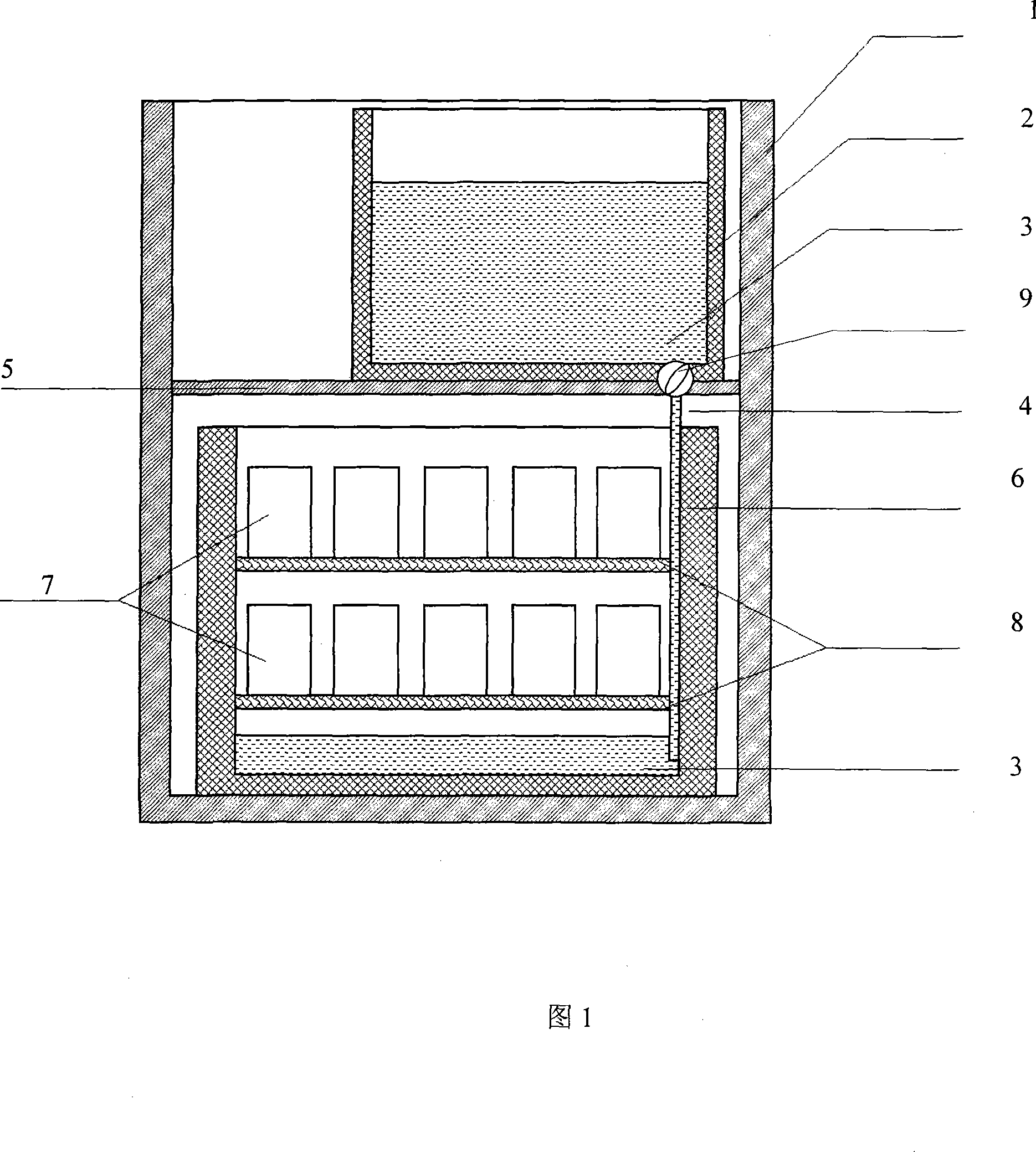
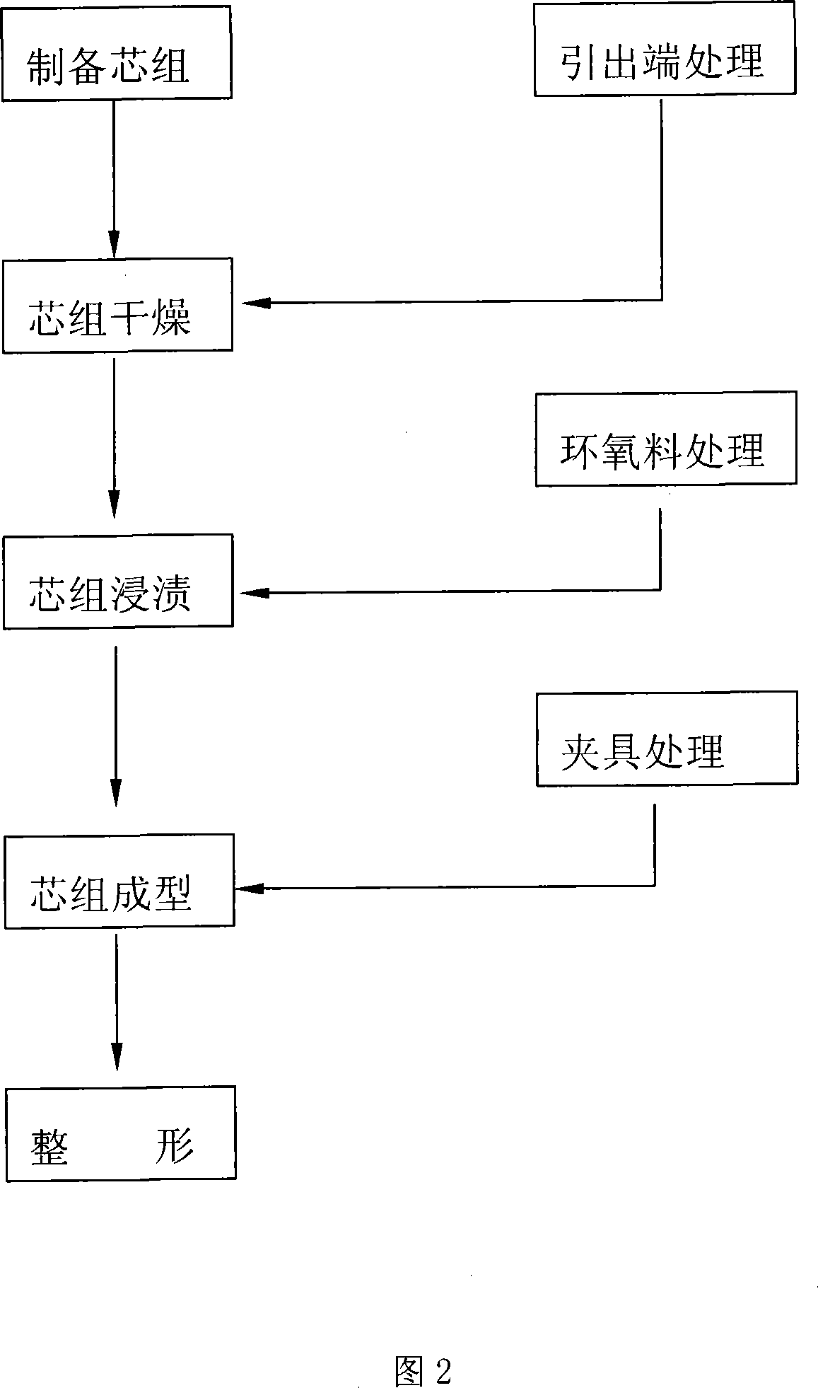
[0026] As shown in Figure 1, the specific implementation is divided into the following steps:

[0027] 1) Prepare the capacitor core group first,

[0028] 2) Prepare the impregnation device and fixture, including impregnation material, porous isolation wire mesh (8), limit washer, and forming press plate for use; the impregnation device includes a material container (1) and a vacuum container (6), and the material container (1) communicates with the vacuum container (6) through the guide rod (4), and the material container (1) is also provided with a discharge valve (9); one end of the guide rod (4) is connected to the vacuum chamber with the core The bottom or inner wall of the container (6) is connected, and the other end is connected with the discharge valve (9);

[0029] 3) Coat the lead part of the core group with an isolating agent to isolate the epoxy resin from the fixture, core, and core metal lead-out parts, reducing the difficulty of subsequent operations. The isol...


PUM


Abstract

The present invention relates to a novel dip forming method of a specific dry-type capacitor. An isolation screen is added. A core group, which dips the dipping material from bottom to upside, is adopted, and a glass rod is used in a diversion step. The core group is thoroughly solidified by the heat preservation of a multi-temperature zone. The purpose of the present invention is to solve the problems of dipping and an encapsulation of the specific capacitors and the relevant electronic equipments. With a strong technical generality, less implementation difficulty, little investment and stable and reliable quality, the dip forming can satisfy the requirements of the electronic equipment of miniaturization, dry-type (solidification), large span of working temperature-zones and strong environmental applicability. The present invention can be used for manufacturing specific capacitors which are applied to high current with high temperature and high voltage, such as a filter capacitor which is used for high-voltage electrical source of airplane, an engine-igniting capacitor, a deep-well pulse sound wave exploration etc. The present invention can also be used in the encapsulation field of high-performance electronic equipment.

Description

Technical field [0001] The invention relates to a dipping and encapsulation molding method for electronic equipment, in particular to a dipping molding method for a capacitor core group. Background technique [0002] The impregnation molding process of special high-voltage pulse capacitors is generally packaged in a metal case or a plastic case, and then impregnated with oil. At present, there are two commonly used methods, one of which is the commonly used wet impregnation process, which generally adopts perfusion and soaking methods, the equipment and operation are complex, time-consuming, energy-consuming, and costly; the other is the conventional dry impregnation molding process. , can only achieve the purpose of perfusion, the exhaust is not thorough, it is very difficult for the impregnating material to infiltrate the inside of the capacitor core group, and the performance and reliability of the product cannot be improved. At the same time, in order to avoid high-temp...

Claims


Application Information

Patent Timeline
IPC IPC(8): B05C3/09B05D1/32B05D3/00B05D7/00H01G13/00
Inventor 曾远柱
Owner CHENGDU HONGMING ELECTRONICS CO LTD
Learn More