Wrist driving structure for industrial robot

An industrial robot and wrist technology, applied in the field of industrial robot wrist drive structure, can solve the problems of large moment of inertia of the wrist unit and difficulty in improving responsiveness, etc.

Active Publication Date: 2008-02-13
FANUC LTD
View PDF2 Cites 27 Cited by
  • Summary
  • Abstract
  • Description
  • Claims
  • Application Information

AI Technical Summary

Problems solved by technology

In addition, since the moment of inertia of the wrist unit increases when the wrist unit is heavy, there is a problem that it is difficult to improve the responsiveness of the control beyond a certain level.

Method used


Image

  • Wrist driving structure for industrial robot
  • Wrist driving structure for industrial robot
  • Wrist driving structure for industrial robot

Examples


Embodiment Construction

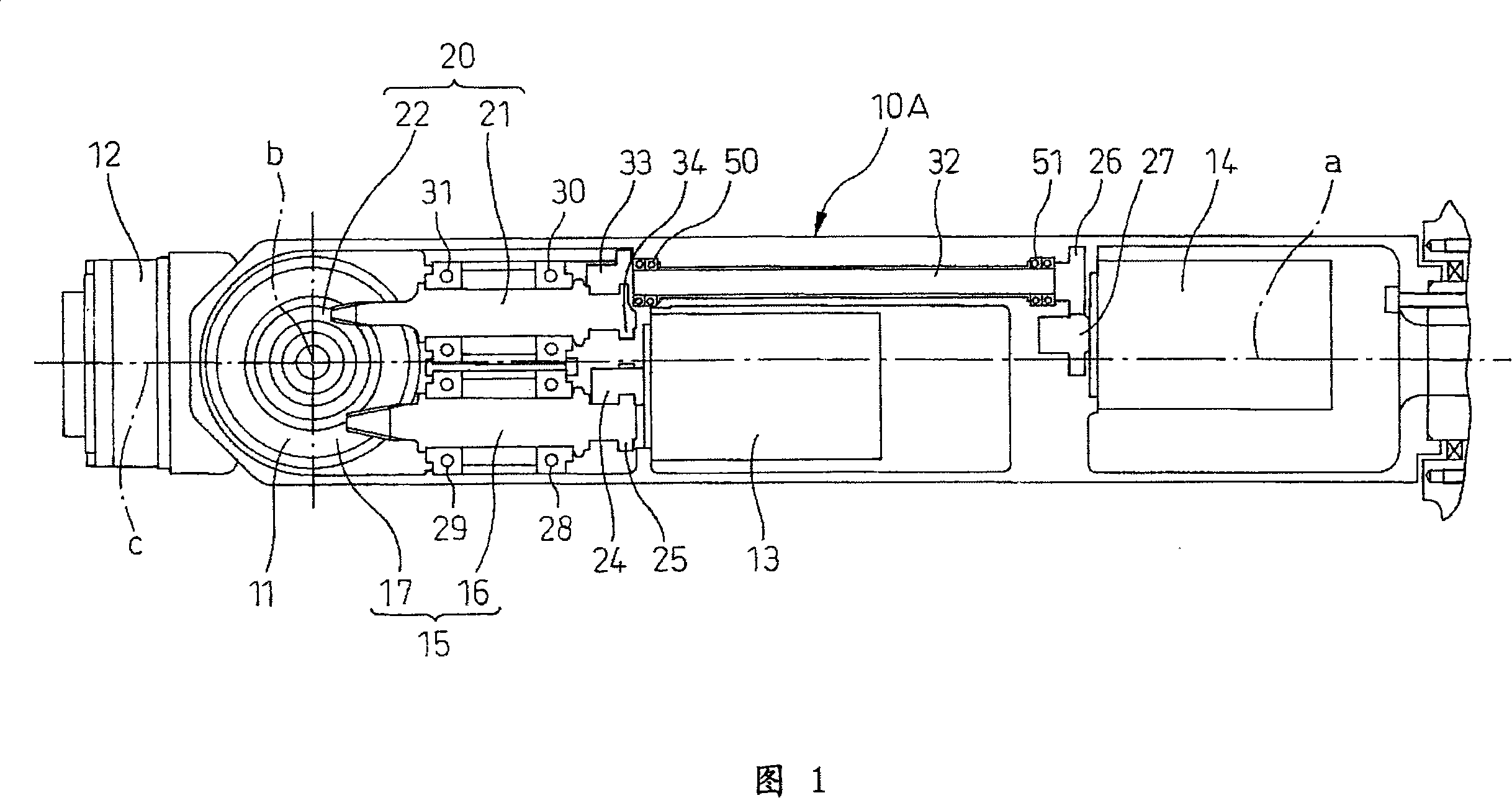
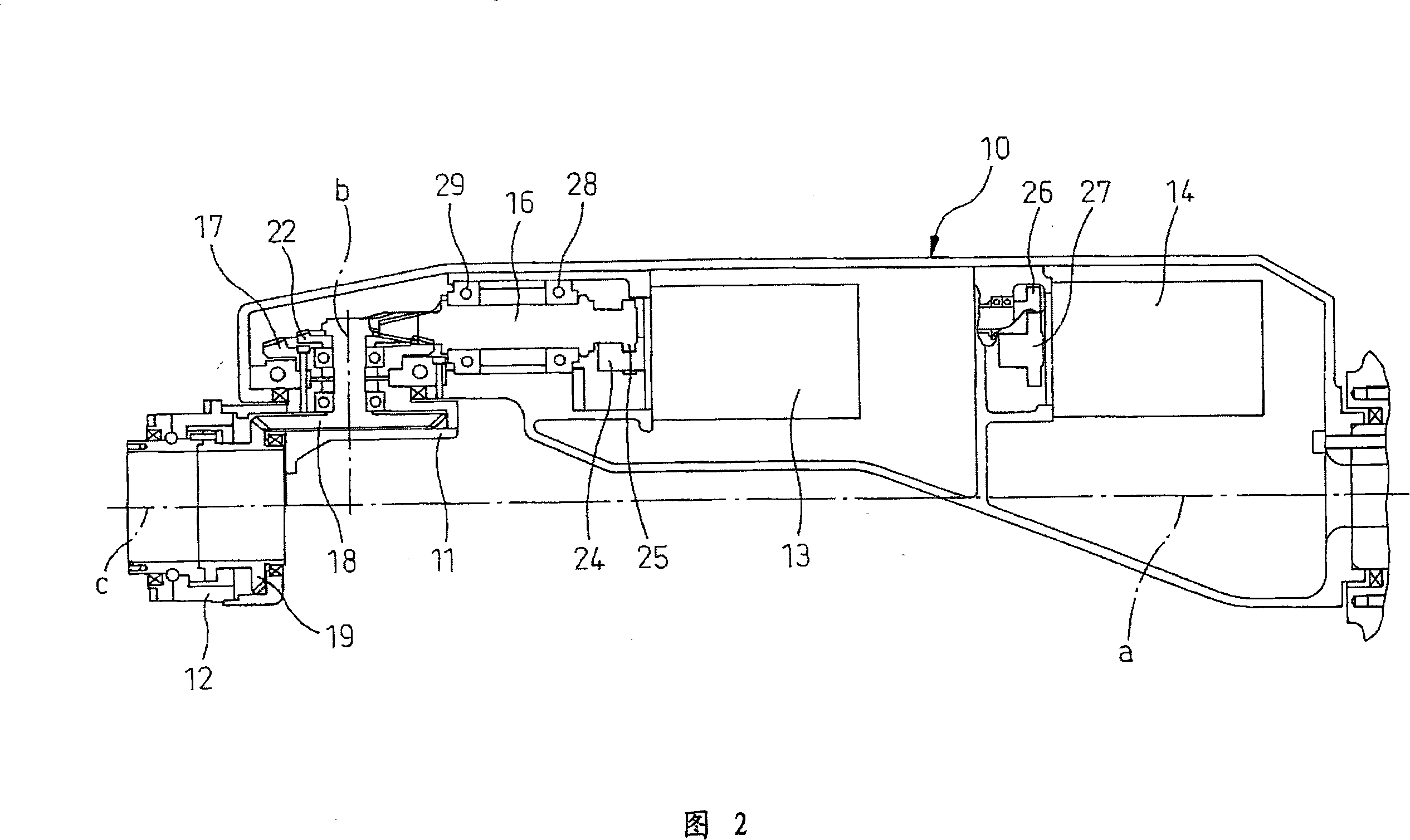
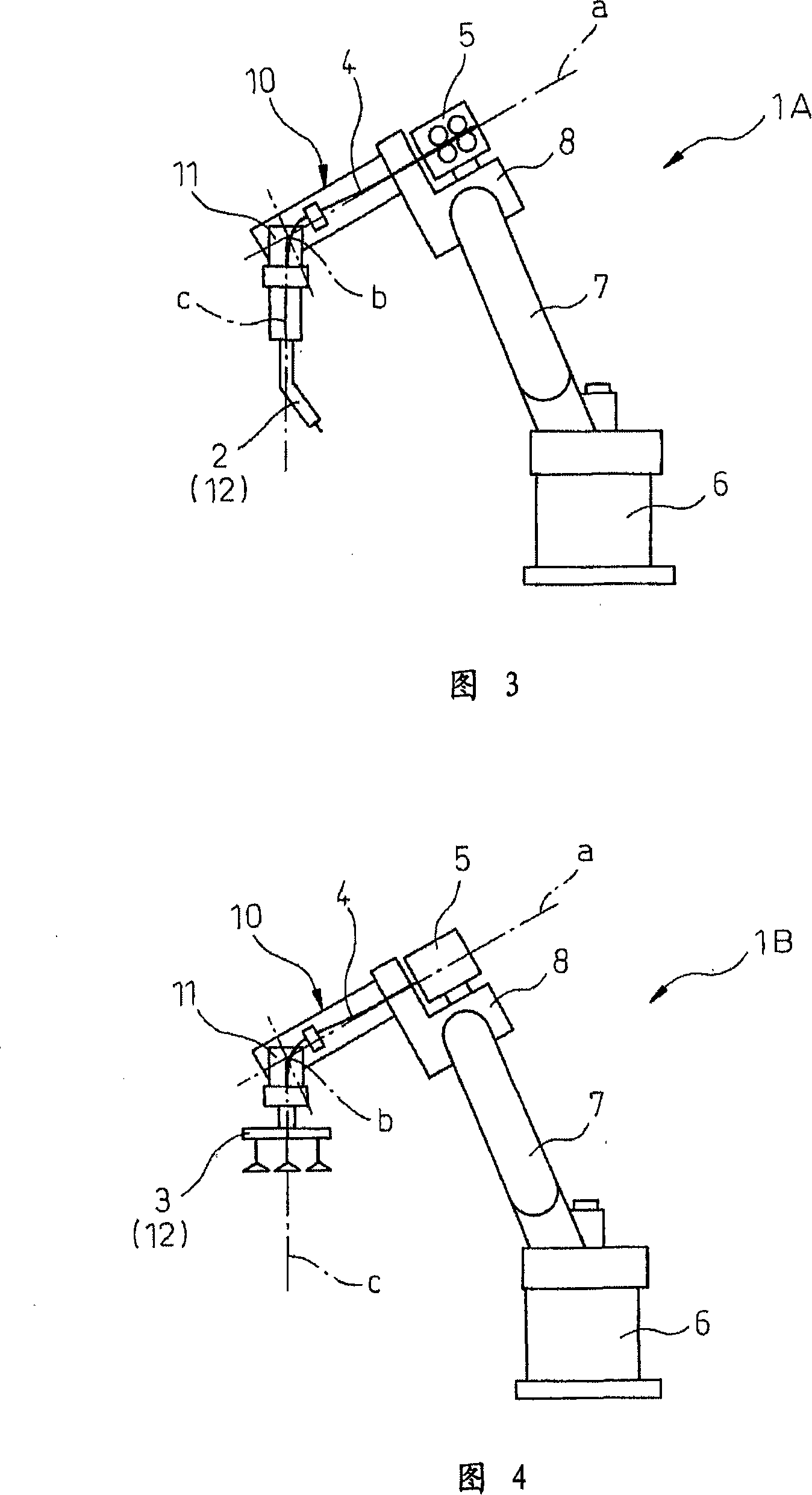
[0019] Specific examples of embodiments of the present invention will be described in detail below with reference to the drawings. 1 and 2 show a first embodiment of the drive structure of an industrial robot arm according to the present invention. 3 and 4 show overall views of an industrial robot to which the arm drive structure of this embodiment can be applied.

[0020] As shown in Fig. 3 and Fig. 4, industrial robot 1A, 1B shown as an example is a robot with degrees of freedom of orthogonal six axes, Fig. 3 is an arc welding robot equipped with welding torch 2 as the wrist unit of the final axis, Fig. Reference numeral 4 is a transfer robot that also includes the manipulator tool 3 . In the arc welding robot 1A, the welding torch 2 is connected to a line 4 for bundling signal cables, power cables, welding wire, gas hoses, welding wire conduits, and the like. In the transfer robot 1B, the manipulator tool 3 is connected to a pipe 4 that bundles signal cables, power cables...


PUM


Abstract

A wrist driving structure for an industrial robot having: a first wrist element supported in cantilever fashion rotatably about a first axis; a second wrist element pivotally supported in cantilever fashion at a distal end side of the first wrist element with a proximal end as a supporting point about a second axis intersecting the first axis; a third wrist element supported in cantilever fashion at a distal end side of the second wrist element rotatably about a third axis intersecting the second axis; two driving motors provided in the first wrist element for driving the second wrist element and the third wrist element, respectively; and two gear sets for reducing a rotational speed of the two driving motors in predetermined reduction ratios. Each of the gear sets has a driving gear driven by one of the two driving motors and a driven ring gear which meshes with the driving gear. Two driven ring gears of the two gear sets are disposed coaxially with the second axis. Two driving gears of the two gear sets are positioned parallel to each other at both sides of the second axis.

Description

technical field [0001] The present invention relates to an industrial robot wrist drive structure provided with a wrist unit which is independently rotatable around mutually intersecting rotation axes and has three degrees of freedom of rotation. Background technique [0002] In general, industrial robots are handled in such a way that many wrist units that move freely with an allowable degree of freedom and pipelines such as electric wires connected to the wrist unit are prevented from interfering with adjacent robots and external devices. In order to improve the production efficiency of the production line in the factory, it is an effective method to arrange more robots in a limited space. For this reason, it is required to provide a robot with a small wrist unit and the pipeline does not extend to the outside of the wrist unit. Industrial robots for out-of-ground processing. [0003] Japanese Patent Application Laid-Open No. 2005-96073 discloses an example of a pipeline ...

Claims


Application Information

Patent Timeline
Patent Type & Authority Applications(China)
IPC IPC(8): B25J17/00B25J19/00
CPCB25J17/0283B25J9/104Y10T74/1913
Inventor 井上俊彦中山一隆岩山贵敏
Owner FANUC LTD
Why Eureka
Try Eureka