
Light source device

A technology of light source device and lamp holder, which is applied in the direction of coupling device, lighting device, light source fixing, etc., and can solve the problems such as unsuitable lamp holder

Active Publication Date: 2008-02-13
ORC MFG
View PDF2 Cites 2 Cited by
  • Summary
  • Abstract
  • Description
  • Claims
  • Application Information

AI Technical Summary

Problems solved by technology

In terms of electrical conductivity and precision, it is not suitable to manufacture lamp holders with convex parts by casting

Method used


Image

  • Light source device
  • Light source device
  • Light source device

Examples


Embodiment Construction

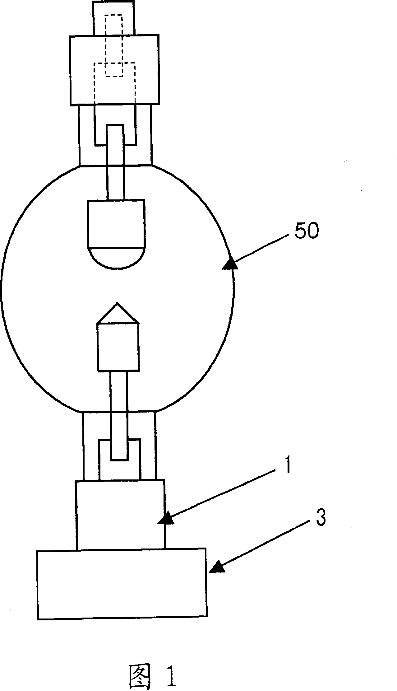
[0026] Next, a preferred mode for implementing the present invention will be described in detail with reference to FIGS. 1 to 7 .

[0027] 【Example】

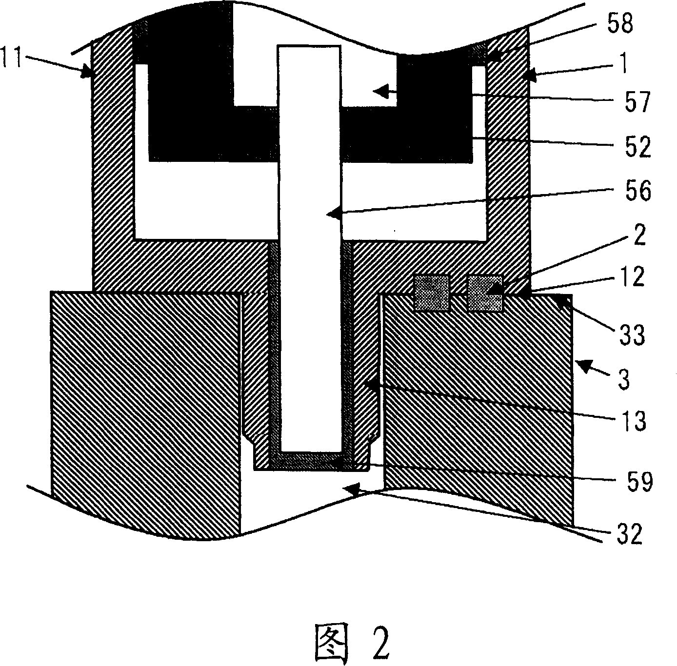
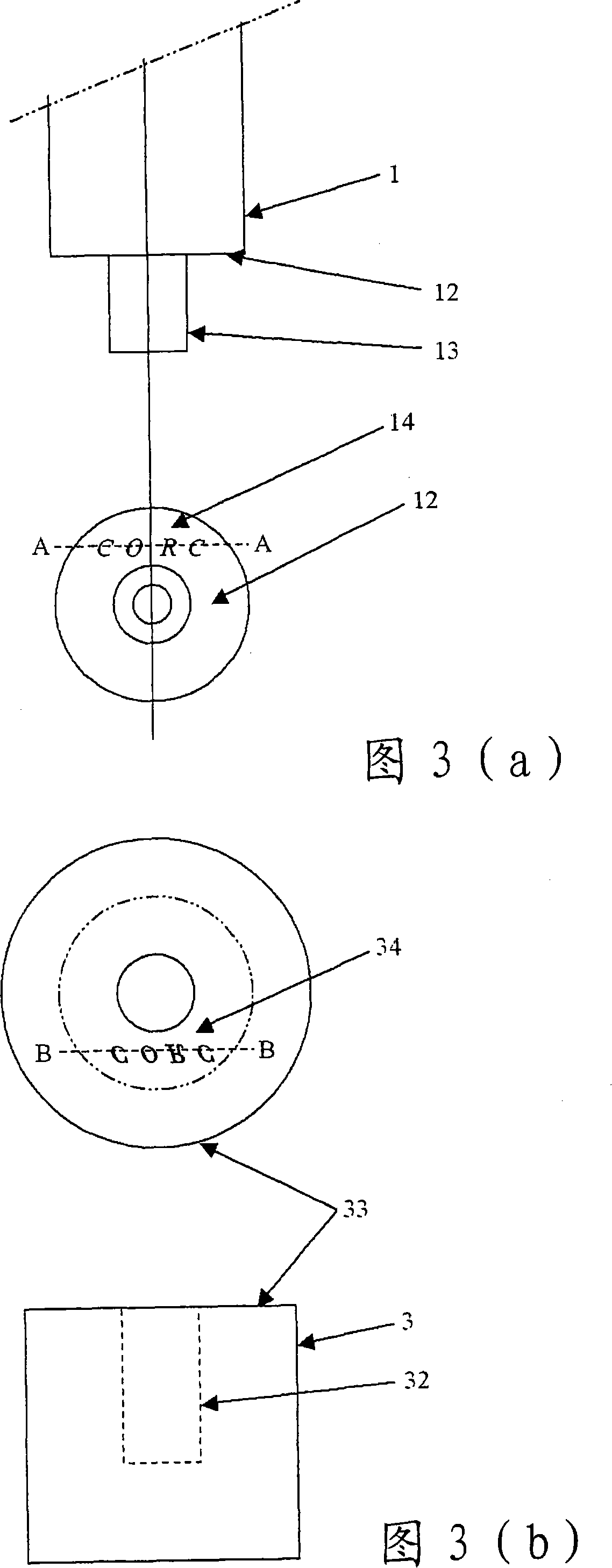
[0028] An embodiment of the present invention is a light source device in which a positive mark is engraved on the end surface of a discharge lamp cap, and a concave portion is engraved with a reverse mark that is mirror-symmetrical to the positive mark on the end face of the base holder holding the cap. , insert a stopper imitating the positive mark between the two concave parts.

[0029] FIG. 1 is an external view of a state where a discharge lamp base structure is attached to a base holder of a light source device according to an embodiment of the present invention. In FIG. 1 , a base structure 1 is a metal base having a large-diameter cylindrical base, a small-diameter base protrusion, and a surface connecting the base and the base protrusion. The base holder 3 is a member that holds the lamp via the base structure. The d...


PUM


Abstract

The invention provides a light source device which can produce a lamp head and a lamp head seat structure correctly installed on the light source device after confirming the suitability of a discharge lamp. Concave portions are formed on the lamp head structure body and the lamp seat, which are mirror symmetry. The concave portion can be accurately produced by the laser processing. A punch is used to die cut the conducting plate with a thickness equal to the depth summation of the concave portions. A block matched with the concave portion is produced and the block is embeded into a second concave portion. If the lamp head structure body is inserted into the lamp head seat, the block embeded in the second concave portion of the lamp head seat is embeded with the first concave portion of the lamp head structure body. The block can position the lamp head structure body and the lamp seat and fix two parts easily and accurately.

Description

technical field [0001] The present invention relates to a light source device, in particular to a light source device in which suitable discharge lamps for generating ultraviolet rays are easily installed. Background technique [0002] Conventionally, in manufacturing processes of semiconductor devices (ICs), liquid crystal panels (LCDs), and printed circuit boards (PCBs), light source devices having discharge lamps that generate ultraviolet rays are used for exposure. As shown in FIG. 8 , this type of discharge lamp is composed of a quartz bulb 5 , an anode 53 , a cathode 54 , an inner guide rod 55 , an outer guide rod 56 , a closed tube 52 and a cap structure 1 . The quartz bulb 5 is composed of a spherical arc tube 51 and two closed tubes 52 . The anode 53 and the cathode 54 are arranged facing each other in the light emitting tube 51 . The anode 53 and the cathode 54 are supported by an inner guide rod 55 and energized. In the closed tube 52, the inner guide rod 55 an...

Claims


Application Information

Patent Timeline
IPC IPC(8): H01J61/02H01R33/05
CPCF21V19/0015F21V19/0025H01J5/48H01J5/50H01J61/86H01R33/05
Inventor 石锅荣彦吉田雄介
Owner ORC MFG
Learn More