Encapsulation method for high-brightness white light LED

A technology of light-emitting diodes and packaging methods, which is applied in the direction of electrical components, electric solid-state devices, circuits, etc., can solve problems such as low production efficiency, application limitations, unfavorable large-scale production, etc., to improve production efficiency, improve uniformity and consistency of light emission sexual effect

Active Publication Date: 2008-02-13
GUANGDONG REAL FAITH LIGHTING TECH
View PDF0 Cites 30 Cited by
  • Summary
  • Abstract
  • Description
  • Claims
  • Application Information

AI Technical Summary

Problems solved by technology

However, this method also cannot ensure that the side of the chip is evenly coated with phosphor; at the same time, because it is difficult to ensure gap-free bonding between the light-emitting chip and the film, the light will be reflected and refracted multiple times on the interface that is not completely bonded. , resulting in a decrease in light extraction efficiency; in addition, since each light-emitting chip has to be pasted with a cured film, the production efficiency is very low, which is not conducive to large-scale production, and this packaging method is only suitable for flip-chips, which is greatly affected by the application. limit

Method used


Image

  • Encapsulation method for high-brightness white light LED
  • Encapsulation method for high-brightness white light LED
  • Encapsulation method for high-brightness white light LED

Examples


Embodiment 1

[0022] Embodiments of the present invention are further described below in conjunction with the accompanying drawings:

[0023] The packaging process is as follows: A. Weld the light-emitting chip or its array to the heat dissipation substrate with IC circuit; B. Align the mold with the light-emitting chip and press it tightly; C. Inject an appropriate amount of fluorescent powder into the mold Potting glue; D. Degassing and curing under vacuum; E. Demoulding.

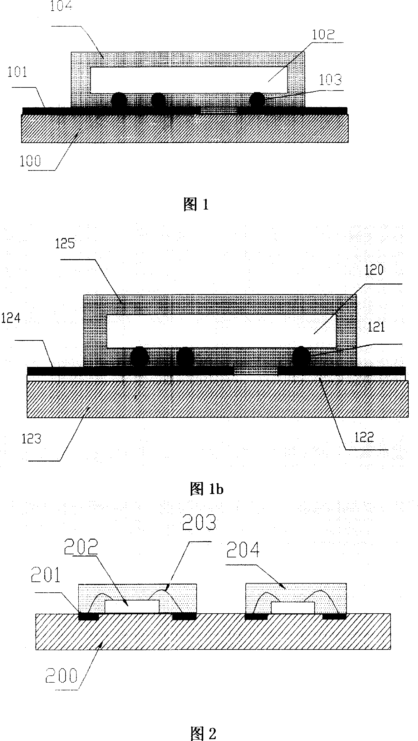
[0024] Referring to FIG. 1 , the figure shows the packaged structure of the flip-chip light-emitting diode chip. The blue light chip 102 is fixed on the silicon substrate or the ceramic substrate 100 by flip-chip soldering balls 103, the silicon substrate or the ceramic substrate 100 is provided with a wire layer 101, and the outer surface of the blue light chip 102 is evenly attached with a ring containing phosphor powder. Oxygen glue or silica gel 104.

[0025] Referring to FIG. 2 , the figure shows the packaged st...

Embodiment 2

[0037] Embodiment 2 is the same as Embodiment 1, the difference is:

[0038] 1. The heat dissipation substrate in Figure 1b is a metal substrate with a passivation layer. The blue light chip 120 is welded on the electrode 124 through flip-chip solder balls 121, the passivation layer 122 is on the metal substrate 123, and the electrode 124 is on the passivation layer 122. The outer surface of the blue light chip 120 is evenly attached with a layer containing Epoxy glue or silica gel 125 for phosphor. See Figure 1b.

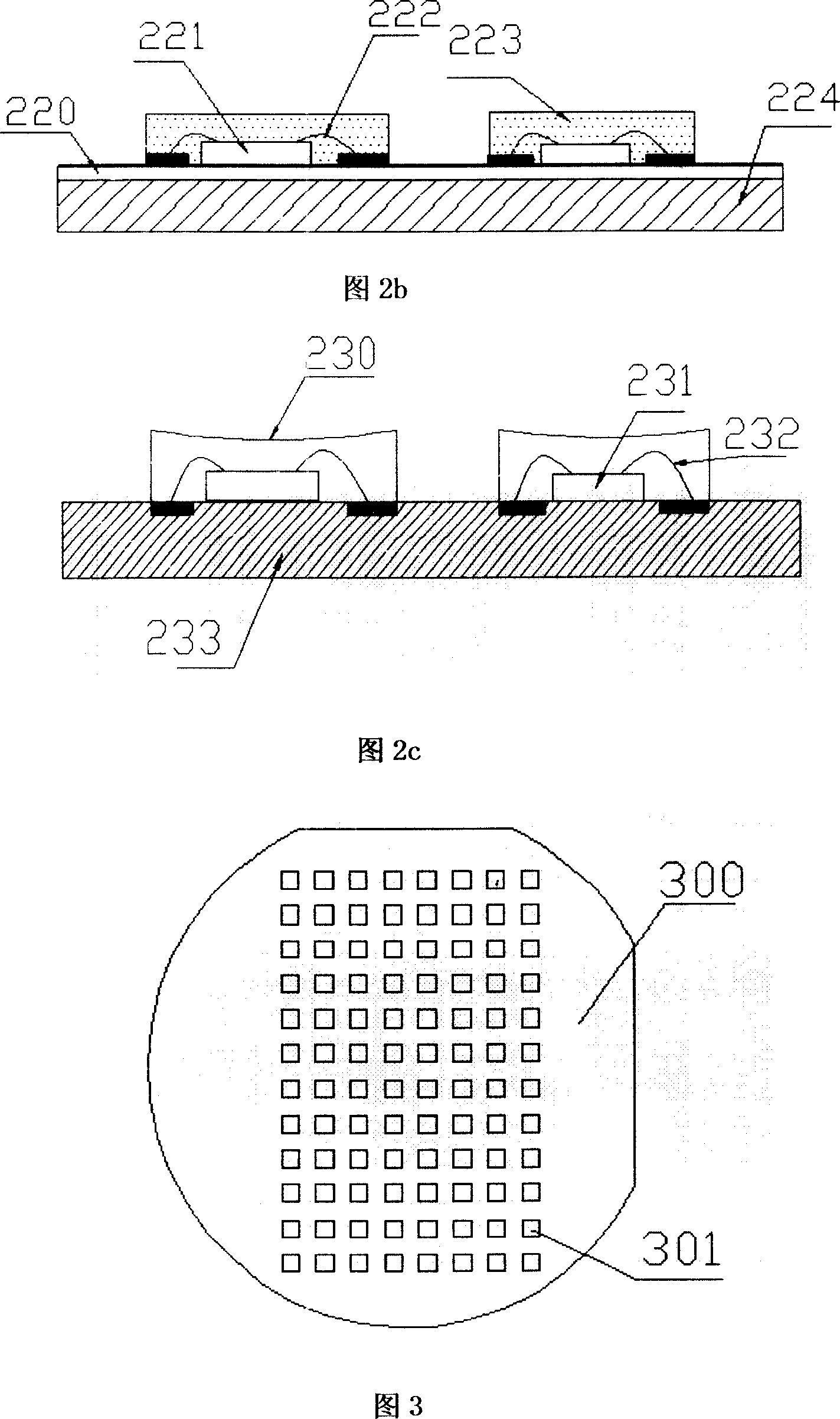
[0039] 2. Figure 2b is a package diagram of a wire-bonded LED chip. The heat dissipation substrate is a metal substrate 224 with a passivation layer. The light emitting diode chip 221 is connected to the electrode through the lead wire 222 , the insulating passivation layer 220 is on the metal substrate 224 , and the light emitting diode chip 221 is bonded and fixed on the insulating passivation layer 220 . A layer of epoxy glue or silica gel 223 containing flu...


PUM


Abstract

A packaging method for high-brightness light-emitting diode of white light mainly comprises a light-emitting diode chip, a radiating substrate and a phosphor glue film. The invention is characterized in that the light-emitting diode chip is welded on the substrate, a mould coated with the mould release is positioned on the radiating substrate by pressurizing, the package resin containing phosphor is poured into the mould, then glue film with uniform thickness and containing phosphor is formed on the upper surface and lateral surface of the light-emitting diode chip after evacuation, solidification and mold release. The invention has the advantages that a glue film containing phosphor with uniform thickness formed on the external surface of the light-emitting diode chip promotes the uniformity and consistency of luminescence from the light-emitting diode chip, and promotes the production efficiency of packaging.

Description

technical field [0001] The invention relates to a packaging technology of a semiconductor device, in particular to a packaging method of a high-brightness white light emitting diode. technical background [0002] The existing high-brightness white light-emitting diode LED is formed by mixing various colors of light. For example, red, green and blue chips are combined to form white light through optical lens, or purple or ultraviolet light is used to excite RGB (red, green and blue) phosphors to obtain white light, or blue light is used to excite yellow phosphors to obtain white light. Among them, the blue light-emitting diode LED chip plus YAG yellow phosphor is used to produce white light. By mixing YAG yellow phosphor into epoxy resin or silica gel, mixing it evenly and coating it on the blue chip by coating or dispensing, However, the disadvantage of this method is that if the coating dose of the yellow phosphor is not controlled accurately during the packaging process, ...

Claims


Application Information

Patent Timeline
Patent Type & Authority Applications(China)
IPC IPC(8): H01L33/00H01L21/50H01L21/56H01L33/48H01L33/50
CPCH01L2224/48091H01L2224/97H01L2924/181H01L2924/00014H01L2924/00012
Inventor 刘胜陈思远罗小兵陈明祥
Owner GUANGDONG REAL FAITH LIGHTING TECH
Why Eureka
Try Eureka