
Circuit module and its making method

A circuit module and power module technology, applied in the direction of printed circuit manufacturing, printed circuit, printed circuit connected with non-printed electrical components, etc. The effect of shortening the current path, saving cost and reducing energy consumption

Inactive Publication Date: 2008-02-13
DELTA ELECTRONICS INC
View PDF0 Cites 3 Cited by
  • Summary
  • Abstract
  • Description
  • Claims
  • Application Information

AI Technical Summary

Problems solved by technology

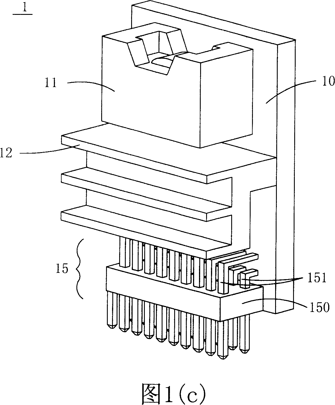
Since the length of the SIP pin 151 is still very long, the problem of increased power consumption still exists
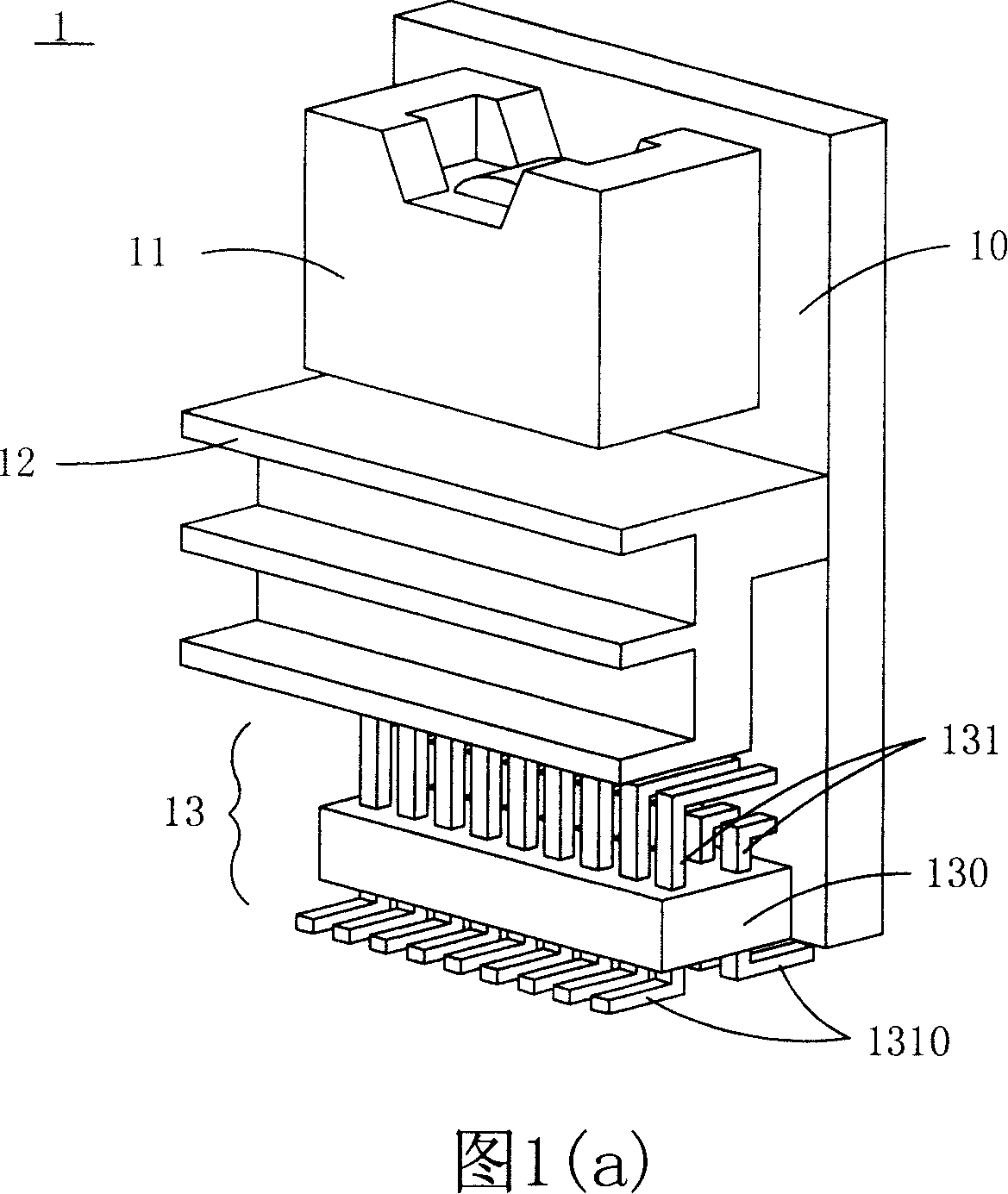
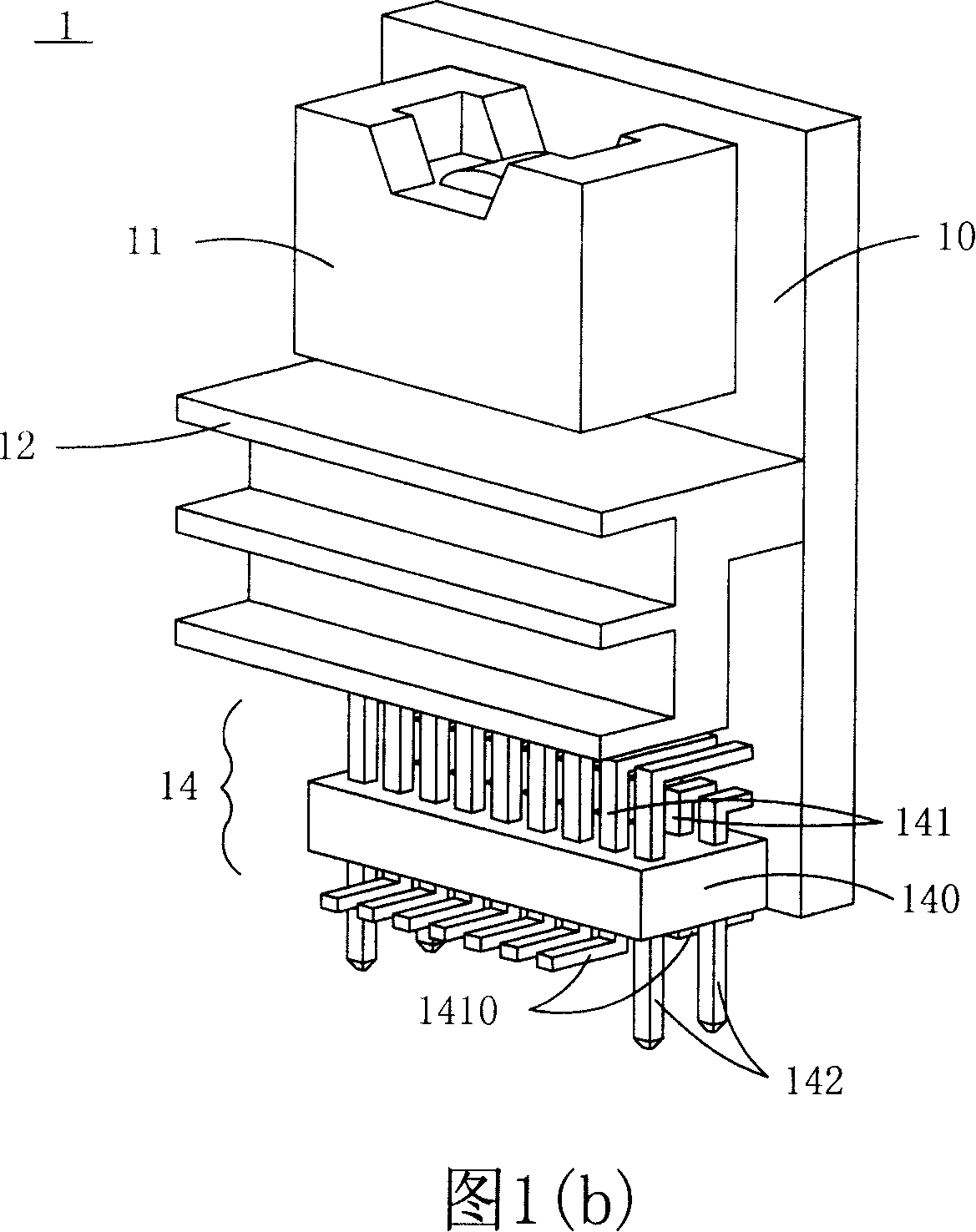
[0007] As mentioned above, the common disadvantage of the known connectors 13, 14, 15 is that the length of the pins is very long, so that the current path increases, resulting in increased energy consumption
In addition, the connectors 13, 14, 15 made by the injection molding process have the disadvantages of high cost and occupying too much space

Method used


Image

  • Circuit module and its making method
  • Circuit module and its making method
  • Circuit module and its making method

Examples


Embodiment Construction

[0069] Some typical embodiments embodying the features and advantages of the present invention will be described in detail in the description in the following paragraphs. It should be understood that the present invention can have various changes in different embodiments without departing from the scope of the present invention, and that the description and illustrations therein are illustrative in nature and not intended to limit the present invention. .

[0070] Please refer to FIG. 2 , which shows a schematic structural diagram of a modularized circuit module in a preferred embodiment of the present invention. As shown in FIG. 2 , the modularized circuit module of the present invention can be, for example, a power module 3 for forming an electrical connection with a system circuit board (not shown in FIG. 2 ). The power module 3 of the present invention includes a printed circuit board 2 composed of a substrate 21 and a circuit pattern 22 , an edge soldering area 23 formed...


PUM


Abstract

The invention discloses a circuit module and the manufacture method of the circuit module applied to be connected with a first contact zone of a system circuit board. The circuit module at least includes a printed wiring board and at least one electronic component arranged on the surface of the electronic component. The printed wiring board is provided with a base board and a circuit pattern; wherein, the base board is provided with at least a surface and a plurality of sides. The circuit pattern is formed on the base board and at least one side of the base board is also provided with a plurality of second contact zones. The a plurality of second contact zones are connected with the circuit pattern and corresponding to the first contact zone of the system circuit board. The invention omits the using of a connector and is contacted with a welding cushion on the system circuit board by the edge of the printed wiring board and thus the invention can save cost and shorten the circuit route thereby reducing the energy consumption of power transmission. Besides, the manufacture mode of the edge jointing zone of the printed wiring board is accomplished by making use of the widely-known plated through hole technique and cutting technique. The method is very easy and can save manufacture time.

Description

technical field [0001] The invention relates to a circuit module and a manufacturing method thereof, in particular to a circuit module used to form an electrical connection with a system circuit board and a manufacturing method thereof. Background technique [0002] With the rapid development of the electronic industry, the internal circuits of many electronic devices have been developed towards modularization, so that many functions are integrated in the circuit board to form a circuit module. Take a common circuit module such as a power module as an example, which includes, for example, a DC to DC converter, a DC to DC converter, etc. Surface Mount Technology (SMT) installs electronic components such as capacitors, resistors, inductors, transformers, diodes, transistors, etc. on the printed circuit board (PWB), and then completes the assembly of the power module. Because the layout design of the power module is more flexible, and can improve the heat dissipation effect of...

Claims


Application Information

Patent Timeline
Patent Type & Authority Applications(China)
IPC IPC(8): H05K1/18H05K1/00H05K3/00H05K13/00
Inventor 郭庆基
Owner DELTA ELECTRONICS INC
Learn More