Casting method for manufacturing layered metal composite material technology and equipment

A layered composite material and composite material technology, applied in the field of laminated metal composite materials, can solve problems affecting product quality, high technical difficulty, narrow application range, etc., and achieve easy product quality, high purity, and wide selection range Effect

Inactive Publication Date: 2008-02-20
丁家伟 +1
View PDF0 Cites 37 Cited by
  • Summary
  • Abstract
  • Description
  • Claims
  • Application Information

AI Technical Summary

Problems solved by technology

However, since the core material casting composite method still does not solve the interface problem, when the outer layer of the composite material is solidified, gas and impurities are easy to accumulate at the interface, which affects the product quality, and the pr

Method used


Image

  • Casting method for manufacturing layered metal composite material technology and equipment
  • Casting method for manufacturing layered metal composite material technology and equipment
  • Casting method for manufacturing layered metal composite material technology and equipment

Examples


Embodiment 1

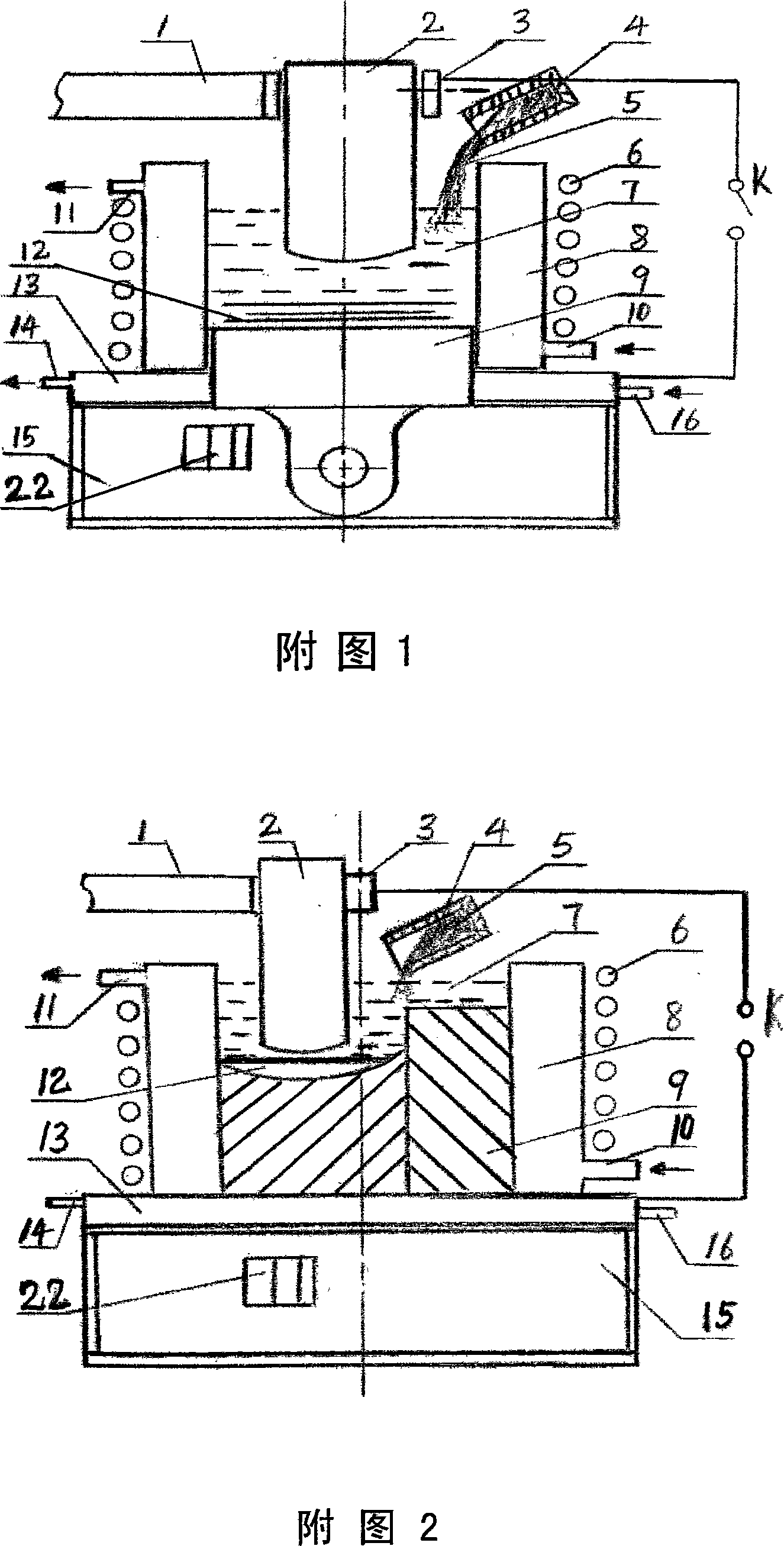
[0023] Embodiment 1: In Fig. 1, this equipment has an equipment base 15, and electroslag furnace 1 is installed beside equipment base 15, and electrode holder 3 is installed on electroslag furnace 1, above electrode holder 3 Electrode 2 is installed, bottom water tank 13 is installed on equipment base 15, water inlet pipe 16 is installed at the bottom of any side of bottom water tank 13, and water outlet pipe 14 is installed at the top of any side of bottom water tank 13, in A water-cooled crystallizer 8 is installed on the top of the bottom water tank 13, a water inlet pipe 10 is installed at the bottom of any side of the water-cooled crystallizer 8, and an outlet pipe 11 is installed on the top of any side of the water-cooled crystallizer 8. The outside of 8 is equipped with electromagnetic induction heater 6, is fixed on equipment base 15 by the center of bottom water tank 13 by composite metal material 9, is equipped with ultrasonic or mechanical vibration equipment 22 on e...

Embodiment 2

[0025] Embodiment 2: In Fig. 2, the difference from Fig. 1 is that the composite material 9 is fixed on the top of the bottom water tank 15, installed on the side of the crystallizer 8, and can be composited into a bimetal composite by repeating the composite process of Embodiment 1 Composite materials and products such as boards. Other processes and equipment are the same as in Embodiment 1, omitted.

Embodiment 3

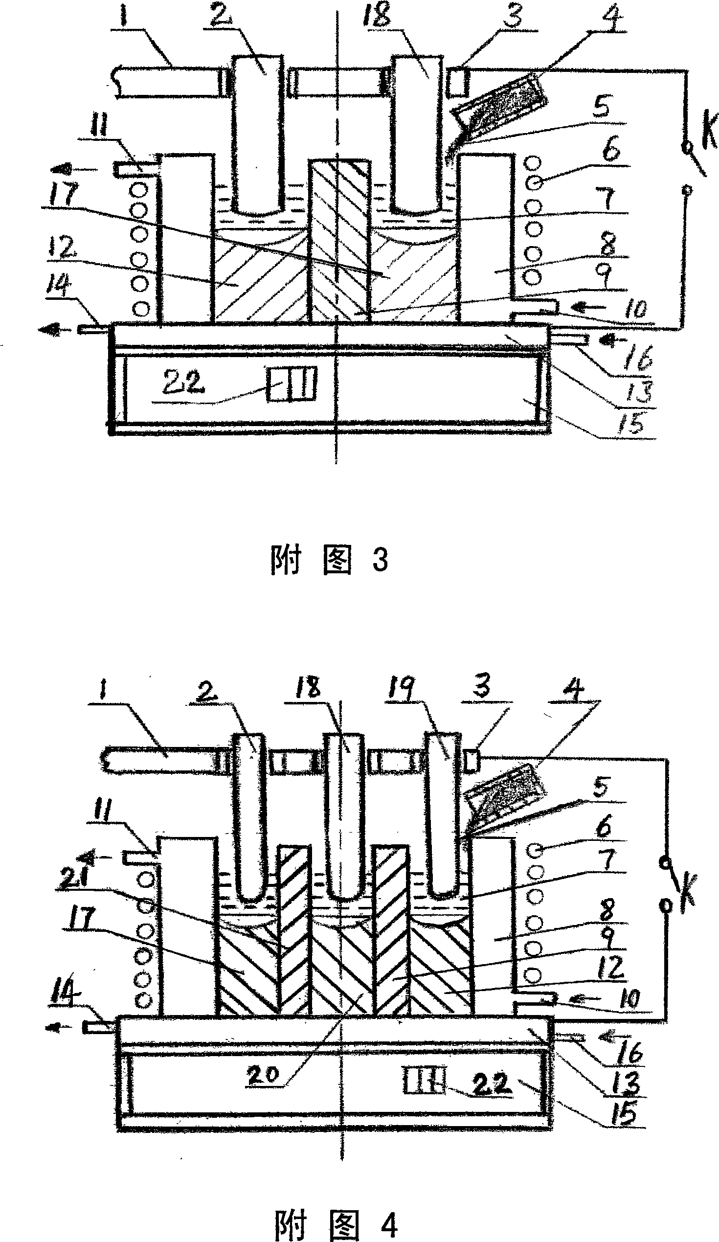
[0026] Embodiment 3: In Fig. 3, the difference from Fig. 2 is that the composite material 9 is fixed on the top of the bottom water tank 15, installed in the middle of the crystallizer 8, and the electrode holder 3 is connected with the electrode 2 and the electrode 18, and the working After starting, electrode 2 and electrode 18 are respectively inserted into the both sides of composite material 9 in the mould, and electroslag heating is carried out, and the composite process of embodiment 1 can be composited into a multilayer containing metal composite materials 17, 9 and 12 Laminated metal composites. Other processes and equipment are the same as in Embodiment 1, omitted.


PUM


Abstract

The present invention discloses a technique and relative equipment for casting laminated and composite metal material. Target material is heated to 300 DEG C to 1200 DEG C by an electromagnetic induction heater installed on exterior of a casting die or a water cooling crystallizer. Molten electroslag liquid is poured in the casting die or the water cooling crystallizer, and an electrode is inserted in for heating. The metal liquid is poured in the casting die or the water cooling crystallizer by top casting mode or bottom casting mode. After casting, the induction heater and the electrode conduct continuous heating for 3 to 20 minutes, then heating is stopped, and layered composite material with plane gradient, laminated composite material and coated composite material of all geometric shapes can be produced. The present invention can simplify production procedures of composite material and can realize the dynamic regulation of all technical parameters during composition. The interface of the composite layer is under eay control so as to achieve excelllent metallurgical combination. The present invention has wide optional range about materal of the composite layer, high productivity, simple production technique and low cost.

Description

technical field [0001] The invention belongs to layered metal composite materials, and the technical field mainly relates to a process and equipment for manufacturing metal layered composite materials by casting method. Background technique [0002] Laminated metal composite materials are various double-layer metal composite materials prepared by using various composite technologies to combine two or more metal materials with different physical, chemical and mechanical properties in layers to achieve firm metallurgical bonding at the interface. Layer or multi-layer gradient layered composite materials, laminated composite materials and coated layered composite materials, although the prepared composite materials still maintain their original characteristics, their physical, chemical and mechanical properties are relatively single The metal material is much superior, so that different parts of the material have different properties, so as to overcome the respective shortcomin...

Claims


Application Information

Patent Timeline
IPC IPC(8): B22D19/16
Inventor 丁家伟丁刚
Owner 丁家伟
Why Eureka
Try Eureka