Multifunctional sounding device and its sounding test method
A testing method and multi-functional technology, applied in soil material testing, measuring devices, using mechanical devices, etc., can solve the problems of inconvenience to continuously measure the dynamic indexes of soil layers on the full-depth profile, difficult to represent shear strength, difficult to implement, etc. Achieve the effect of eliminating difficulties and uneconomical, without increasing the process and labor intensity, and with a small distance between measuring points
- Summary
- Abstract
- Description
- Claims
- Application Information
AI Technical Summary
Problems solved by technology
Method used
Image
Examples
Embodiment 1
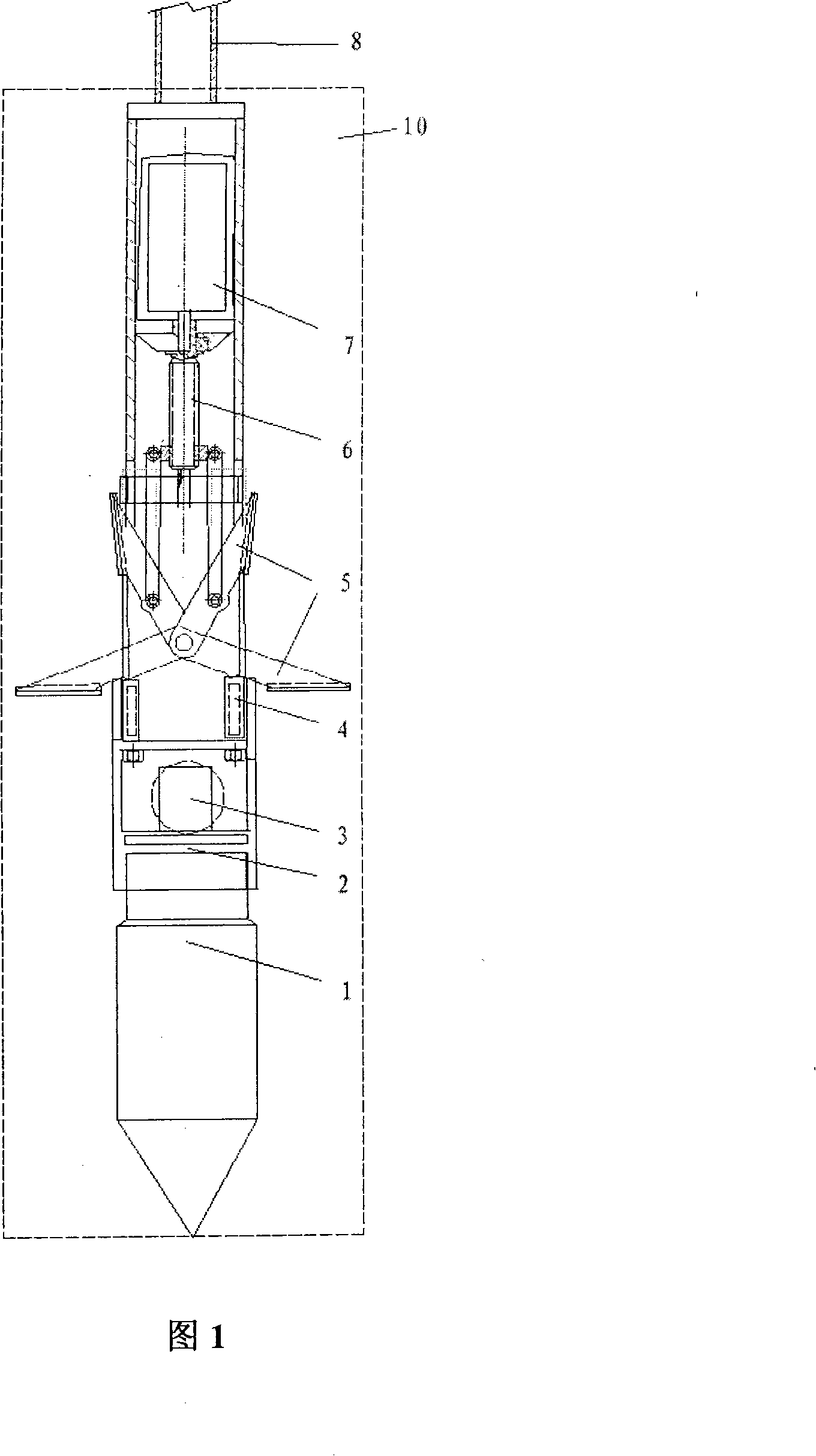
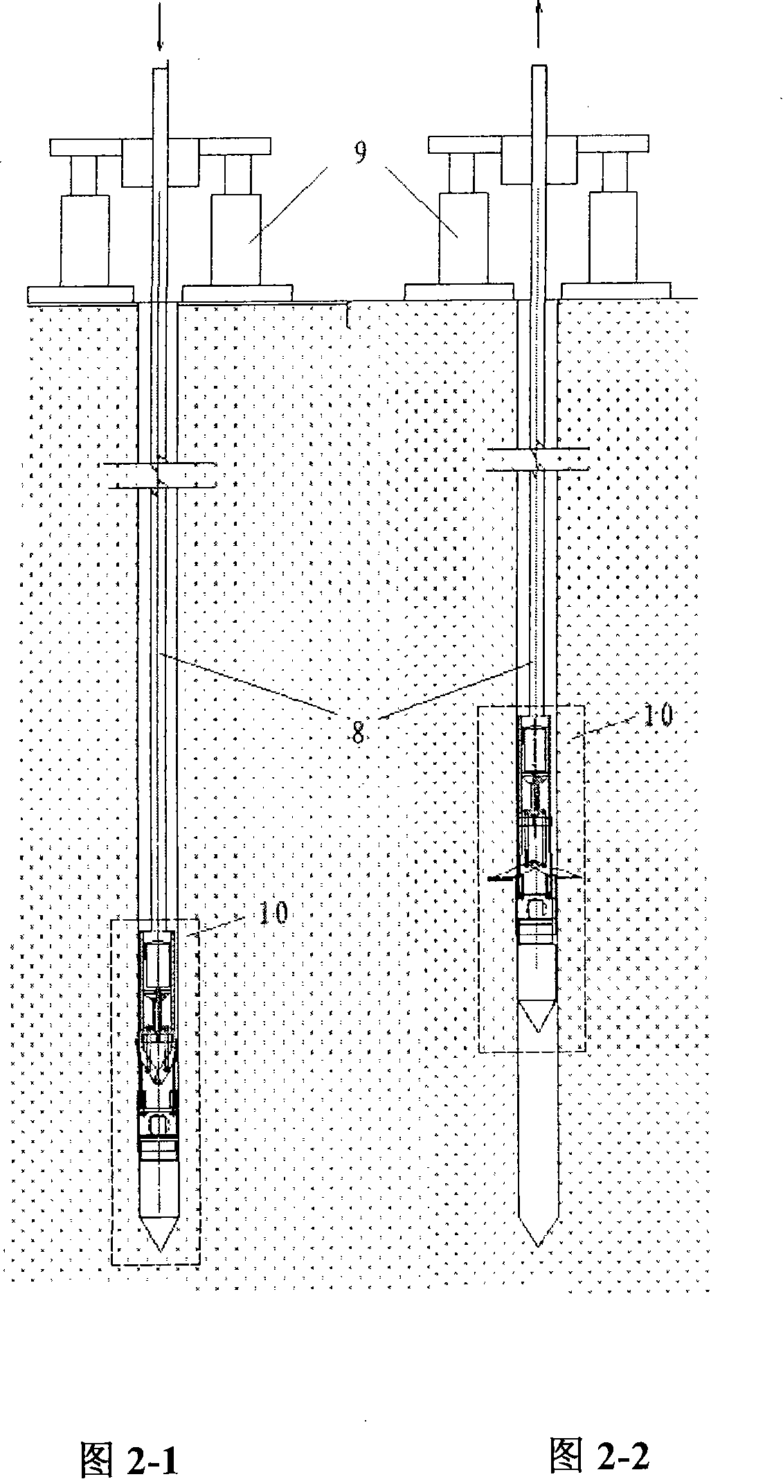
[0062] Such as figure 1 As shown, the multifunctional penetrating device of the present invention includes: a combined probe 10 and a probe rod 8; a single bridge probe 1 that is conical and contains a hollow column strain sensor is provided at the end of the combined probe 10 ; The upper end of the single bridge probe 1 is a connection device 2, a multi-directional wave detection device 3, a force sensor 4, and a puncher 5, and a drive shaft frame 6 and a drive motor 7 are provided on the puncher 5. Wherein, the load cell 4 is used to measure the force value of the puncher 5;
[0063] A cable is provided in the combined contact probe 10, one end of which is connected to the electrical signal connection equipment of the single bridge probe 1, the multidirectional wave detection device 3, the load cell 4 and the driving motor 7; the other end is drawn out and connected to the ground respectively. The secondary instrument and electronic control equipment are connected; the vibr...
Embodiment 2
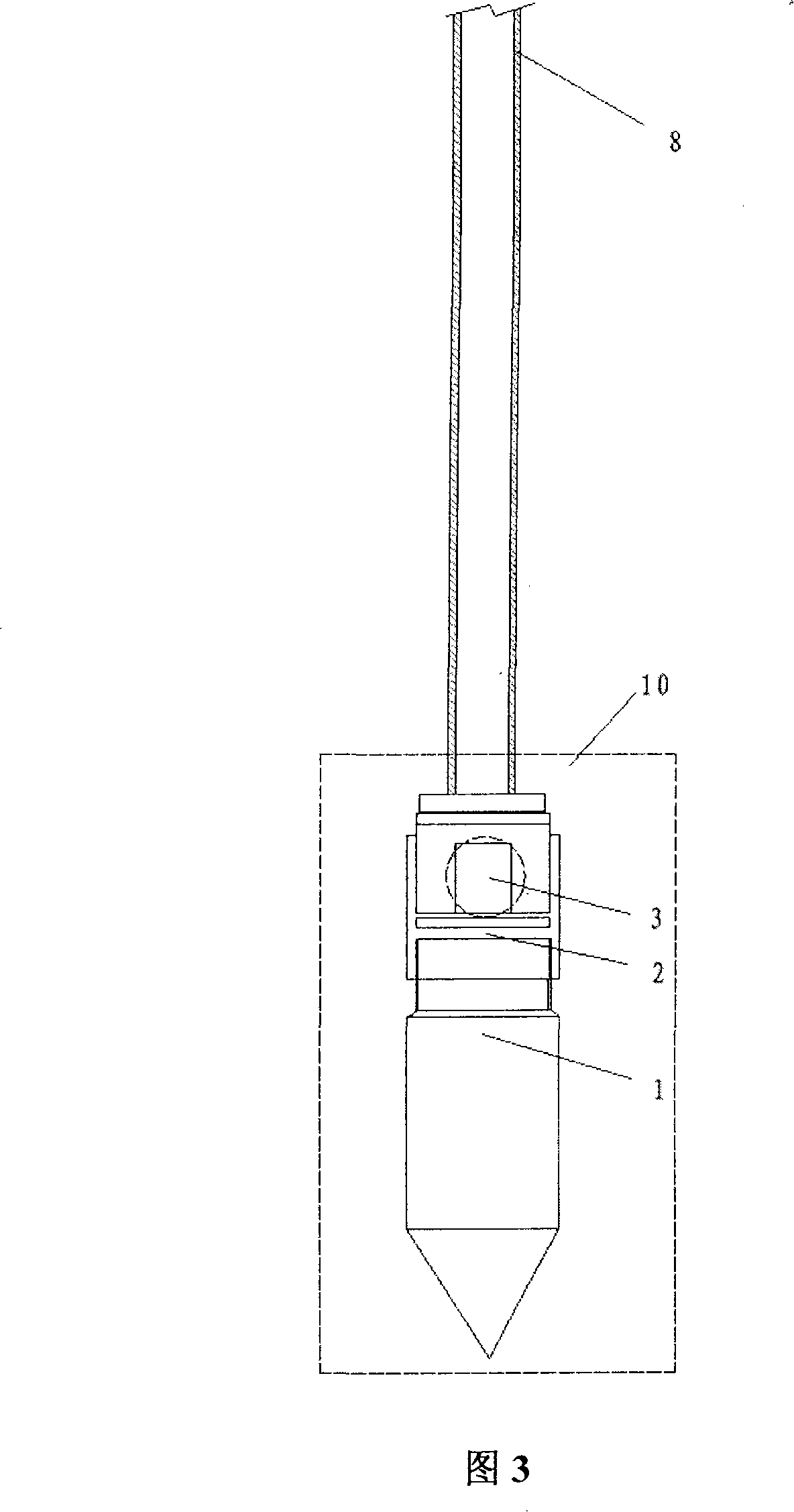
[0080] Such as image 3 As shown, the multifunctional penetrating device of the present invention includes: a combined probe 10 and a probe rod 8; a single bridge probe 1 that is conical and contains a hollow column strain sensor is provided at the end of the combined probe 10 ; On the upper end of the single-bridge probe 1 is the connecting device 2 and the multi-directional wave detection device 3 ;
[0081] A cable is arranged in the combined contact probe, and one end thereof is connected with the single bridge probe 1 and the multi-directional wave detecting device 3; the other end leads out to be connected with the secondary instrument on the ground; The source device is connected to the secondary meter.
[0082] The multi-directional wave detection device 3 adopts an electromagnetic speed pendulum, and the output voltage is transmitted to the secondary instrument on the ground.
[0083] The tube of the multi-directional wave detection device 3 is a demagnetized metal tu...
Embodiment 3
[0092] Such as Figure 4 As shown, the multifunctional penetrating device of the present invention includes: a combined probe 10 and a probe rod 8; a single bridge probe 1 that is conical and contains a hollow column strain sensor is provided at the end of the combined probe 10 ; The upper end of the single bridge probe 1 is the connecting device 2, the load cell 4, and the punching device 5, and the driving shaft frame 6 and the driving motor 7 are arranged on the punching device 5. Wherein, the load cell 4 is used to measure the force value of the puncher 5;
[0093] A cable is arranged in the combined contact probe, and one end thereof is connected with the electric signal connection equipment of the single bridge probe 1, the load cell 4 and the driving motor 7; connect.
[0094] The punching and shearing device 5 is two force-applying ends of wedge-shaped section, which take the central axis as the axis, and form a force-measuring lever with the force point located in t...
PUM
 Abstract
Description
Claims
Application Information
 - R&D
- Intellectual Property
- Life Sciences
- Materials
- Tech Scout
- Unparalleled Data Quality
- Higher Quality Content
- 60% Fewer Hallucinations
Browse by: Latest US Patents, China's latest patents, Technical Efficacy Thesaurus, Application Domain, Technology Topic, Popular Technical Reports.
© 2025 PatSnap. All rights reserved.Legal|Privacy policy|Modern Slavery Act Transparency Statement|Sitemap|About US| Contact US: help@patsnap.com


