
Liquid crystal display unit

A liquid crystal display device and liquid crystal cell technology, applied in optics, instruments, nonlinear optics, etc., can solve the problems of color doping of reflected light, large wavelength dependence of anti-reflection effect, poor productivity, etc., and achieve a wide viewing angle and display quality. Good effect with excellent damage resistance

Inactive Publication Date: 2008-02-20
MATSUSHITA ELECTRIC WORKS LTD +1
View PDF6 Cites 7 Cited by
  • Summary
  • Abstract
  • Description
  • Claims
  • Application Information

AI Technical Summary

Problems solved by technology

However, this laminated antireflection layer has a large wavelength dependence of the antireflection effect, and the display device using the antireflection layer has the problem that the reflected light is colored and has a viewing angle dependence.
Moreover, when a large-area multilayer film is formed using a vacuum device that manufactures it, the productivity is poor

Method used


Image

  • Liquid crystal display unit
  • Liquid crystal display unit
  • Liquid crystal display unit

Examples


Embodiment

[0205] Hereinafter, the present invention will be described in more detail using examples, but the present invention is not limited to the following examples. However, parts and % are based on weight unless otherwise specified.

[0206] In addition, in an Example and a comparative example, measurement and evaluation were performed by the following method.

[0207] (1) Thickness

[0208] After embedding the optical laminate in epoxy resin, it was cut into a thickness of 0.05 μm using a microtome (manufactured by Yamato Industries, Ltd., RUB-2100), and the cross-section was observed and measured using a scanning electron microscope. For laminates, measurements are made for each layer.

[0209] (2) Refractive index

[0210] Under the conditions of temperature 20°C±2°C and humidity 60±5%, use an automatic birefringence meter (manufactured by Oji Scientific Instruments Co., Ltd., KOBRA-21) to determine the in-plane retardation of the optical anisotropic body at a wavelength of 5...

manufacture example 1

[0238] (Manufacturing example 1) Production of original film

[0239] For norbornene-based polymer (trade name: ZEONOR 1420R, manufactured by ZEON Co., Japan, glass transition temperature: 136° C., saturated water absorption: less than 0.01% by weight) pellets were dried at 110° C. using a hot air drier with circulating air for 4 Hour. Then, using a polymer filter (filter precision 30 μm) in the shape of a leaf disc, and having an average surface roughness Ra=0.04 μm plated with chrome at the front end of the die lip, and a T-die of the coating hanger type with a lip width of 650 mm A single-screw extruder was used to melt-extrude the pellets at 260° C. to obtain an original film with a thickness of 200 μm and a width of 600 mm.

manufacture example 2

[0240] (Production Example 2) Production of Optically Anisotropic Body 1

[0241] Using a biaxial stretching machine, the oven temperature (preheating temperature, stretching temperature, heat setting temperature) is 138°C, the film extrusion speed is 1m / min, the movement accuracy of the chuck is within ±1%, and the longitudinal stretching ratio is 1.41 times 1. Under the condition that the transverse stretch ratio is 1.41 times, the original film obtained in Production Example 1 was simultaneously biaxially stretched to obtain an optically anisotropic body 1 with a thickness of 100 μm. The main refractive index of the obtained optical anisotropic body 1, n x =1.53068, n y =1.53018, n z = 1.52913.


PUM

PropertyMeasurementUnit
thicknessaaaaaaaaaa
diameteraaaaaaaaaa
thicknessaaaaaaaaaa

Abstract

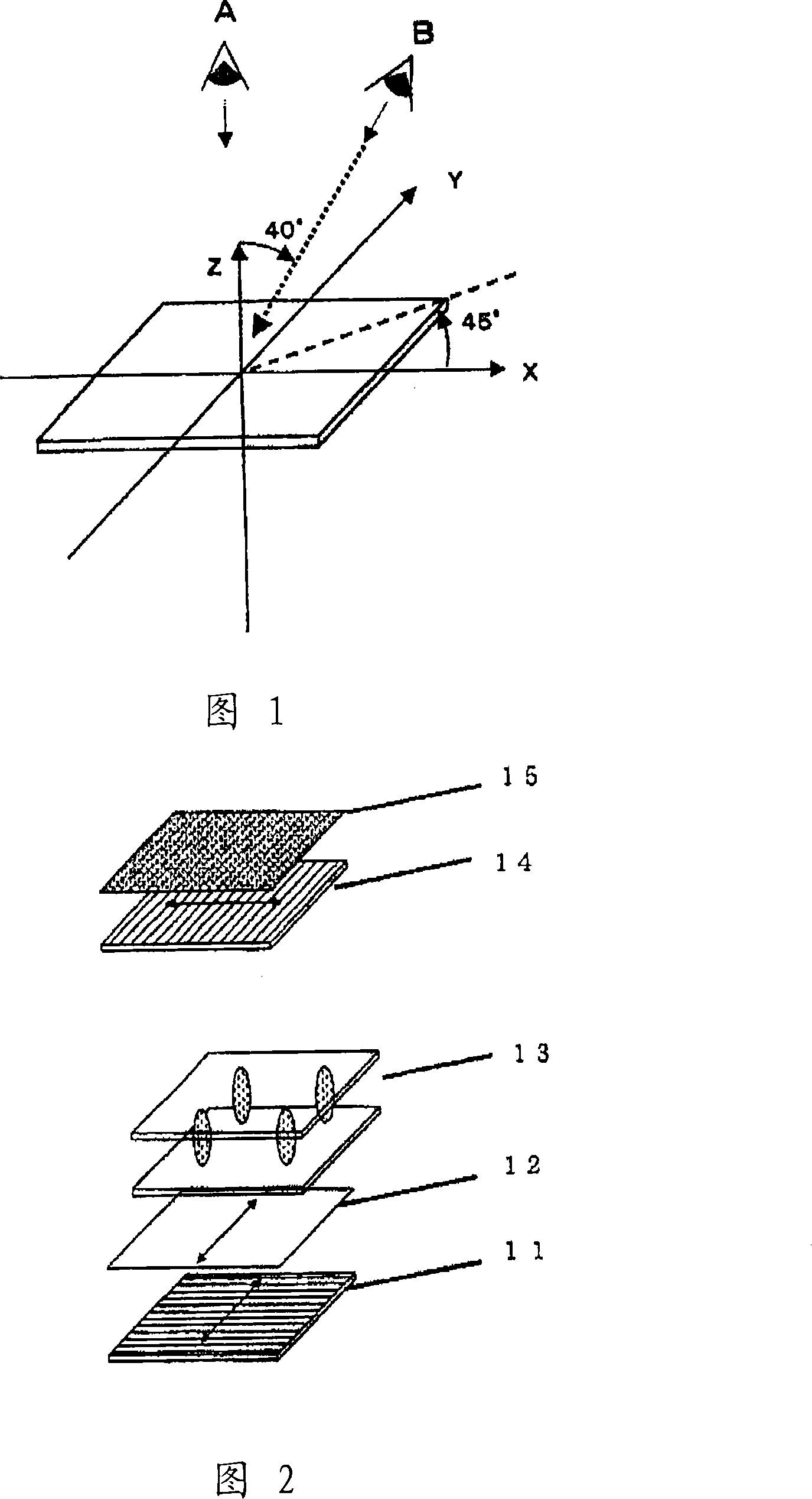
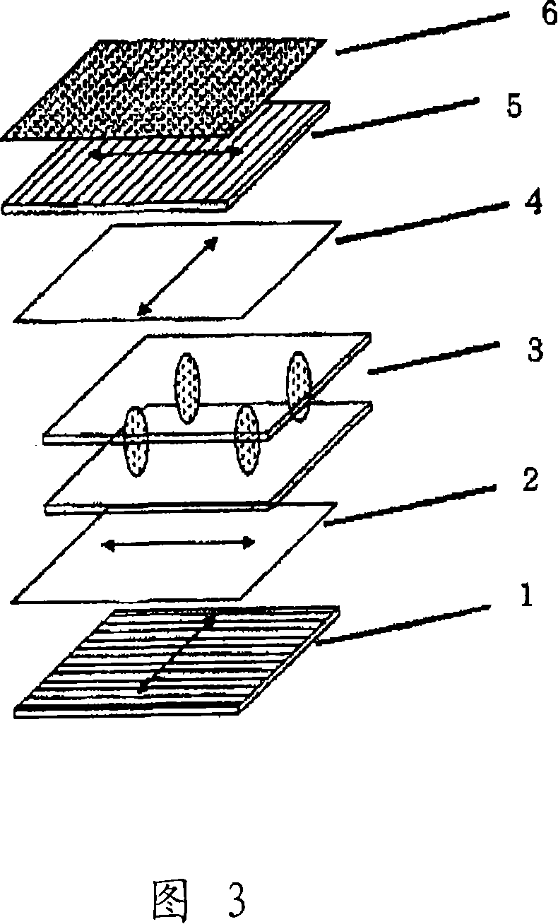
A vertical alignment (VA)-mode liquid crystal display unit comprising, arranged in layers in the order mentioned, a low-refractive-index layer, an output-side polarizer, at least one sheet of biaxial optical anisotropy, a liquid crystal cell and an input-side polarizer, wherein (1) nx>ny>nz is satisfied (nx, ny: in-plane main refractive index of the whole optical anisotropy, nz: thickness-direction main refractive index), (2) the low-refractive-index layer consists of aero-gel with a refractive index of up to 1.37, and (3), when no voltage is applied with the biaxial optical anisotropy and the liquid crystal cell stacked by excluding the output-side polarizer and the input-side polarizer, retardation R0 when a light with a wavelength of 550nm is incident from a normal direction and retardation R40 when a light with a wavelength of 550nm is incident from a direction of a polar angle of 40 degrees satisfy the relation | R40 - R0 | = 35 nm.

Description

technical field [0001] The present invention relates to a liquid crystal display device. More specifically, the present invention relates to a liquid crystal display device having a wide viewing angle, no reflection, excellent scratch resistance, good black display quality when viewed from any direction, uniformity, and high contrast. Background technique [0002] Conventionally, a so-called TN mode in which liquid crystal having positive dielectric constant anisotropy is horizontally aligned between two substrates has been mainly used as a liquid crystal display device (hereinafter abbreviated as LCD). However, in this TN mode, even if black display is attempted, light leakage occurs as a result of birefringence caused by liquid crystal molecules near the substrate, making it difficult to perform complete black display. [0003] In contrast, in the vertical alignment mode, which is the so-called VA (Vertical Alignment) mode, since the liquid crystal molecules are aligned a...

Claims


Application Information

Patent Timeline
Patent Type & Authority Applications(China)
IPC IPC(8): G02F1/13363G02F1/1335G02B1/11G02B5/30B82Y20/00G02B1/111
CPCG02F2413/01G02F2201/50G02F1/133502G02F1/133634G02F2413/12G02F2413/02G02F2001/133742G02F1/133742G02B5/30G02F1/13363
Inventor 山木健之横川弘辻本光福崎僚三丰嶋哲也吉原真纪荒川公平
Owner MATSUSHITA ELECTRIC WORKS LTD
Learn More