Jet printing valve based on carbon nano-tube tiny bubble generator and method of producing the same

A technology of micro-bubble generator and carbon nanotubes, which is applied in printing and other directions, can solve the problems of high power consumption, achieve low power consumption, overcome high power consumption, and have wide application prospects

Inactive Publication Date: 2008-02-27
HUAZHONG UNIV OF SCI & TECH
View PDF0 Cites 6 Cited by
  • Summary
  • Abstract
  • Description
  • Claims
  • Application Information

AI Technical Summary

Problems solved by technology

The micro-bubble generator is the core of the thermal printing system. At present, most of the micro-heaters based on traditional metal materials are used, and the power consumption is relatively large.

Method used


Image

  • Jet printing valve based on carbon nano-tube tiny bubble generator and method of producing the same
  • Jet printing valve based on carbon nano-tube tiny bubble generator and method of producing the same
  • Jet printing valve based on carbon nano-tube tiny bubble generator and method of producing the same

Examples


Embodiment 1

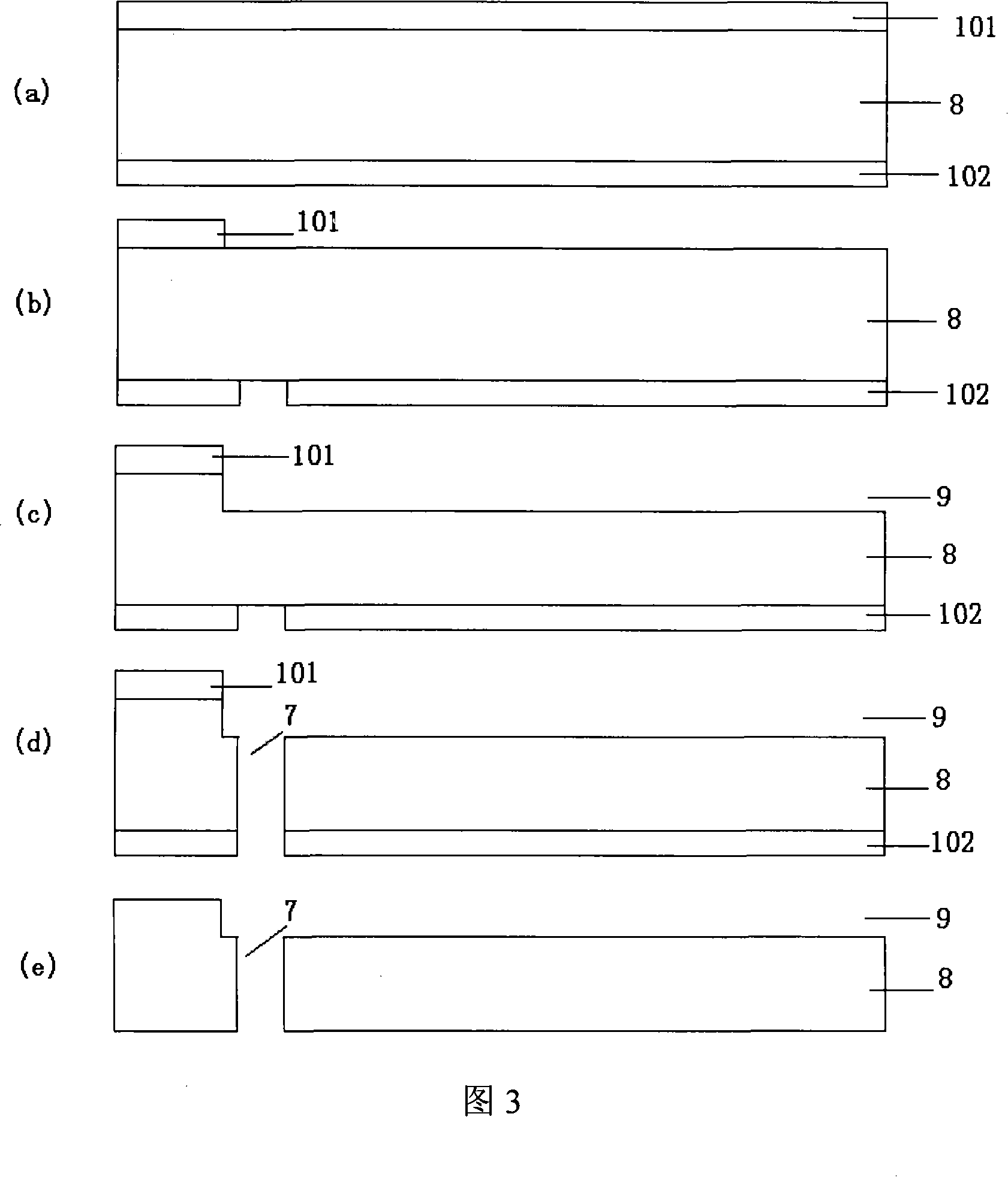
[0046] (1) Surface treatment and cleaning of the glass substrate 1 according to a standard CMOS process;

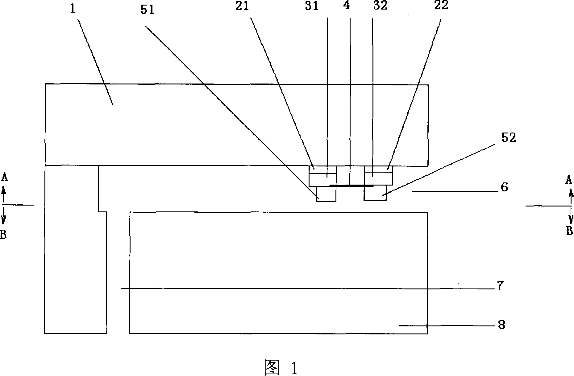
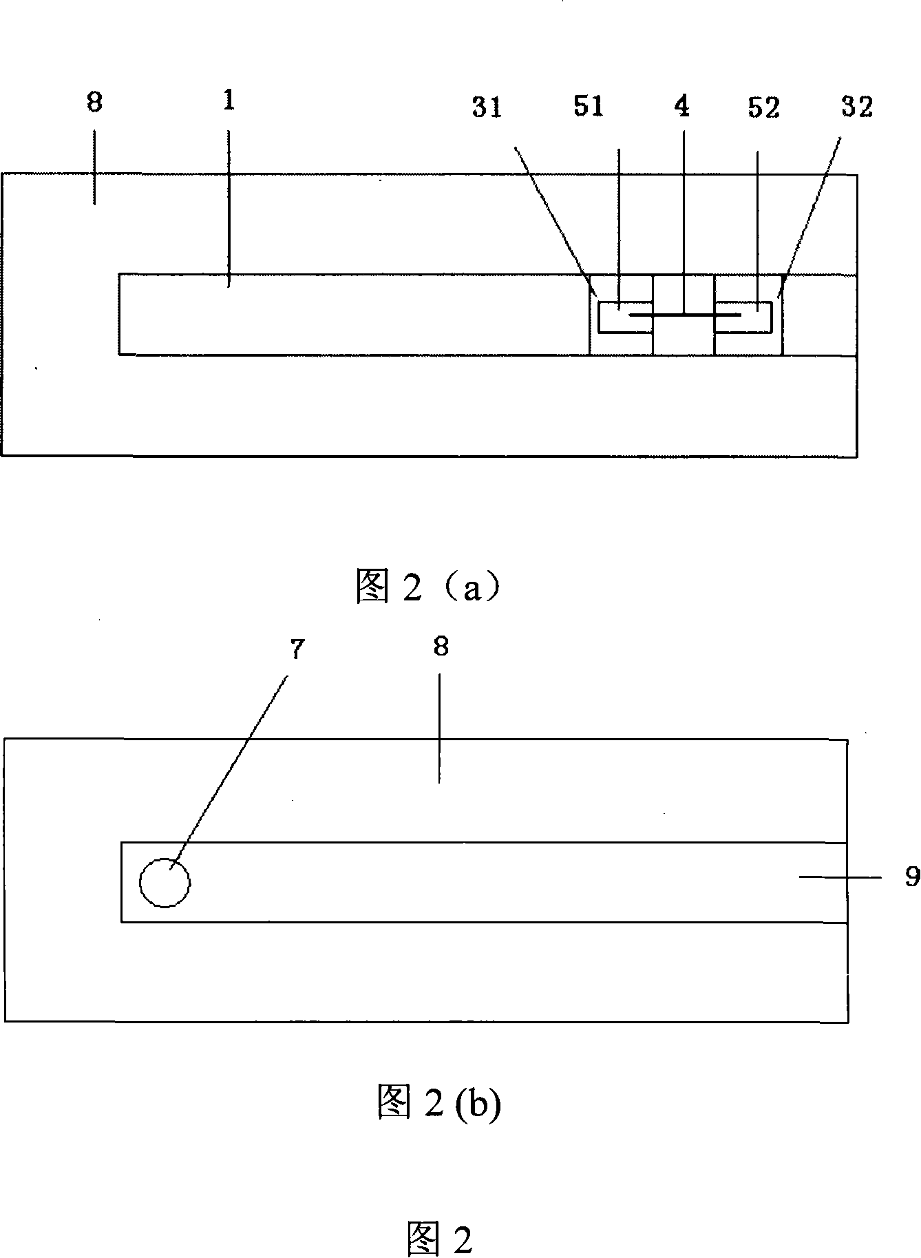
[0047] (2) The carbon nanotube microbubble generator is prepared on the glass substrate 1, and the process is as follows:

[0048] (2.1) Evaporating titanium with an electron beam to form a titanium film with a thickness of 20nm;

[0049](2.2) Evaporating gold by electron beam to form a gold film with a thickness of 400nm;

[0050] (2.3) Form gold electrodes 31, 32 using the existing lift-off process (lift-off), and the distance between the gold electrodes 31, 32 is 5 μm;

[0051] (2.4) Mix carbon nanotubes 4 with a diameter of 10 to 30 nm and absolute ethanol solvent in a ratio of 0.01 mg / ml, and disperse the carbon nanotubes uniformly through ultrasound;

[0052] (2.5) 1MHz, 8V AC voltage is loaded between the gold electrodes 31 and 32 on the glass substrate 1, and the carbon nanotube suspension is dropped between the electrodes with a micro-syringe. When the solvent ...

Embodiment 2

[0064] (1) Surface treatment and cleaning of the glass substrate 1 according to a standard CMOS process;

[0065] (2) The carbon nanotube microbubble generator is prepared on the glass substrate 1, and the process is as follows:

[0066] (2.1) Adopt sputtering titanium to form a titanium film with a thickness of 30nm;

[0067] (2.2) Adopt sputtering gold to form a gold film with a thickness of 300nm;

[0068] (2.3) Form gold electrodes 31, 32 using the existing lift-off process (lift-off), and the distance between the gold electrodes 31, 32 is 1 μm;

[0069] (2.4) Mix carbon nanotubes 4 with a diameter of 10 to 30 nm and absolute ethanol solvent in a ratio of 0.005 mg / ml, and disperse the carbon nanotubes uniformly by ultrasonication;

[0070] (2.5) 0.5MHz, 5V AC voltage is loaded between the gold electrodes 31 and 32 on the glass substrate 1, and the carbon nanotube suspension is dropped between the electrodes with a micro-injector. When the solvent evaporates completely, t...

Embodiment 3

[0082] (1) surface-treating and cleaning the silicon substrate 1 with the oxide layer grown therein according to the standard CMOS process;

[0083] (2) The carbon nanotube microbubble generator is prepared on the glass substrate 1, and the process is as follows:

[0084] (2.1) Adopt sputtering titanium to form a titanium film with a thickness of 30nm;

[0085] (2.2) Adopt sputtering gold to form a gold film with a thickness of 300nm;

[0086] (2.3) Form gold electrodes 31, 32 using the existing lift-off process (lift-off), and the distance between the gold electrodes 31, 32 is 10 μm;

[0087] (2.4) Mix carbon nanotubes 4 with a diameter of 10 to 30 nm and absolute ethanol solvent in a ratio of 0.05 mg / ml, and disperse the carbon nanotubes uniformly through ultrasound;

[0088] (2.5) 0.8MHz, 10V AC voltage is loaded between the gold electrodes 31 and 32 on the glass substrate 1, and the carbon nanotube suspension is dropped between the electrodes with a micro-injector. When ...


PUM

PropertyMeasurementUnit
thicknessaaaaaaaaaa
thicknessaaaaaaaaaa
diameteraaaaaaaaaa

Abstract

The invention discloses a spraying and printing valve of micro bubble generator based on carbon nano-tube and the preparing method. The spraying and printing valve comprises glass substrate or silicon substrate of micro bubble generator with carbon nano-tube and silicon bottom substrate by micro machining. The micro bubble generator with carbon nano-tube is constituted by carbon nano-tube, two golden electrodes and silicon dioxide layer. The carbon nano-tube is set between two golden electrodes. The silicon dioxide layer is covered at the position where the carbon nano-tube is contacted with two golden electrodes. Via hole is set on the silicon bottom substrate as fluid inlet pipe and groove connected with the fluid inlet pipe is set on the surface of silicon bottom substrate. The substrate is bonded with the silicon bottom substrate so as to make the micro bubble generator with carbon nano-tube face to the groove to form nozzle. The preparing method is that the micro bubble generator with carbon nano-tube is prepared on the substrate; fluid inlet pipe and groove are prepared on the silicon bottom substrate; they are bonded together. The invention conquers the shortage that power consumption of conventional micro bubble generator is large and possesses the potentiality of good high density integration. The invention has a wide application prospect in advanced manufacturing field.

Description

technical field [0001] The invention belongs to the technical field of micro-electromechanical systems, and in particular relates to a jet printing valve based on a carbon nanotube micro-bubble generator and a preparation method thereof. technical background [0002] The application of jet printing technology in the preparation of devices, especially some large-area devices such as displays and adaptive distributed antennas, has attracted more and more attention. Compared with the planar process lithography technology, the advantages of jet printing technology are: no special requirements for the substrate, and suitable for flexible materials; due to the designability of the structure of the nozzle and its movement, the graphics can be formed directly according to the design, and the graphics of jet printing are flexible. , less raw material consumption, low total cost. In addition, jet printing can provide non-contact micro-dispensing of various liquids, such as biological...

Claims


Application Information

Patent Timeline
Patent Type & Authority Applications(China)
IPC IPC(8): B41J2/14B41J2/16B41J2/05
Inventor 周文利高俊雄王耘波朱文锋于军
Owner HUAZHONG UNIV OF SCI & TECH
Why Eureka
Try Eureka