Built-in coupling optical ring cavity device

A technology of annular cavity and coupling light, applied in the direction of coupling of optical waveguide, etc., can solve the problems of complex process, and achieve the effect of simplifying film structure, improving coupling efficiency and low loss

Inactive Publication Date: 2008-02-27
ZHEJIANG UNIV
View PDF0 Cites 5 Cited by
  • Summary
  • Abstract
  • Description
  • Claims
  • Application Information

AI Technical Summary

Problems solved by technology

However, the biggest problem is that its process is relatively complicated, requiring multiple thin film deposition, photolithography, etching and surface planarization

Method used


Image

  • Built-in coupling optical ring cavity device
  • Built-in coupling optical ring cavity device
  • Built-in coupling optical ring cavity device

Examples


Embodiment Construction

[0017] Further illustrate the present invention below in conjunction with accompanying drawing.

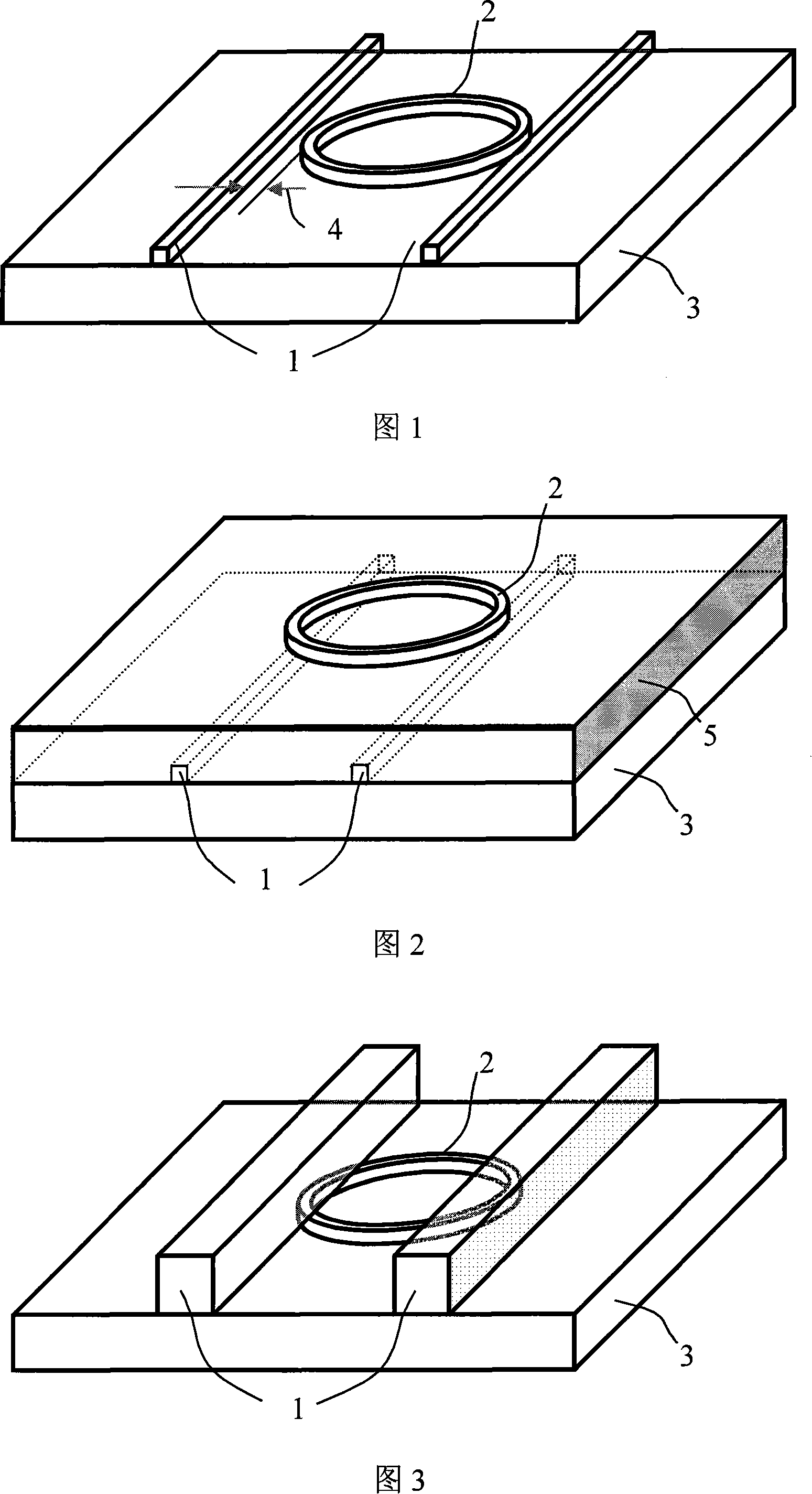
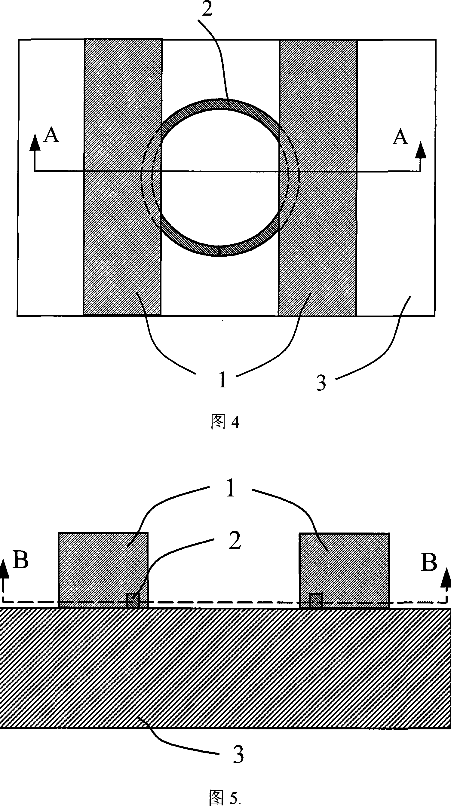
[0018] Referring to FIGS. 3 to 6 , the embedded coupling optical ring cavity device of the present invention includes a coupling optical waveguide 1 , a ring cavity optical waveguide 2 and a substrate isolation layer 3 . The coupling optical waveguide 1 and the ring cavity optical waveguide 2 share the substrate isolation layer 3 , and the ring cavity optical waveguide 2 is embedded in the coupling optical waveguide 1 in the coupling region between the ring cavity optical waveguide 2 and the coupling optical waveguide 1 .

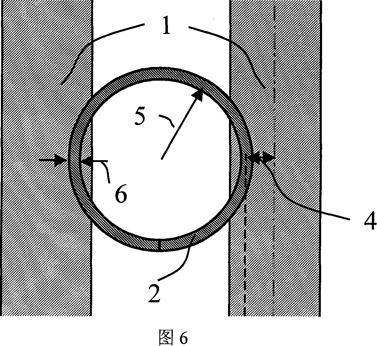
[0019] By changing the center distance 4 between the coupling optical waveguide 1 and the ring cavity optical waveguide 2 (see FIG. 6 ), different coupling coefficients between the ring cavity optical waveguide 2 and the coupling optical waveguide 1 can be obtained.

[0020] By changing the bending radius 5 of the ring cavity optical waveguide 2 (see FIG. 6 ), ...


PUM


Abstract

The invention is the embedded coupling optics ring cavity apparatus including the underlay isolating layer, the ring cavity optical waveguide and the coupling optical waveguide. The coupling optical waveguide uses the same underlay isolating layer with the ring cavity optical waveguide. In the coupling region, the ring cavity waveguide is embedded into the coupling optical waveguide. Because of sharing the underlay isolating layer, it can simplify the film structure in height direction and only needs the underlay isolating layer, the ring cavity optical guide core and coupling optical waveguide core. The process is more simplifier than the traditional 'vertical coupling'. It can reach the ring cavity with small bending diameter; also it can improve the coupling efficient with the optical fiber to save energy cost. By changing the coupling optical waveguide and the ring cavity optical waveguide, it can adjust the coupling efficient in a large range to meet the different characters of apparatus.

Description

technical field [0001] The invention relates to the field of planar optical waveguide integrated devices, in particular to an embedded coupling optical ring cavity device. Background technique [0002] Optical ring cavity device is a photonic device that has a very important position and significance in the field of photonic signal processing. Optical ring cavity devices usually include a ring cavity (such as a microresonator ring or a microdisk), and one or two coupling optical waveguides. In order to make it have a larger free spectral range, the circumference of the entire annular cavity must be reduced. Therefore, a strongly confined optical waveguide should be used to form an annular cavity with a small bending radius, for example, based on SOI (Silicon-on-insulator, silicon on insulator) nano-optical waveguide annular cavity (Little et.al. "Ultra-compact Si / SiO.sub.2 micro-ring resonator channel dropping filter", IEEE Photon.Tech.Lett., vol.10, pp.549-551, 1998). I...

Claims


Application Information

Patent Timeline
Patent Type & Authority Applications(China)
IPC IPC(8): G02B6/26
Inventor 戴道锌
Owner ZHEJIANG UNIV
Why Eureka
Try Eureka