Elevator control apparatus

A technology for elevator control and equipment, applied in elevators, transportation and packaging, etc., can solve the problems of consuming regenerative energy, increasing the size of elevator control equipment, increasing the manufacturing cost of elevator control equipment, etc.

Active Publication Date: 2008-03-05
TOSHIBA ELEVATOR KK
View PDF1 Cites 22 Cited by
  • Summary
  • Abstract
  • Description
  • Claims
  • Application Information

AI Technical Summary

Problems solved by technology

[0009] However, dynamic braking configured as above requires load resistors that consume regenerative energy generated in the motor, contacts that disconnect each load resistor from the power line during normal operation, and disconnect the motor and load resistors from the inverter during braking. contact
As a result, the manufacturing cost of the entire elevator control device is increased, and the size of the elevator control device is increased

Method used


Image

  • Elevator control apparatus
  • Elevator control apparatus
  • Elevator control apparatus

Examples


Embodiment 1

[0022] A first embodiment of the present invention will be explained.

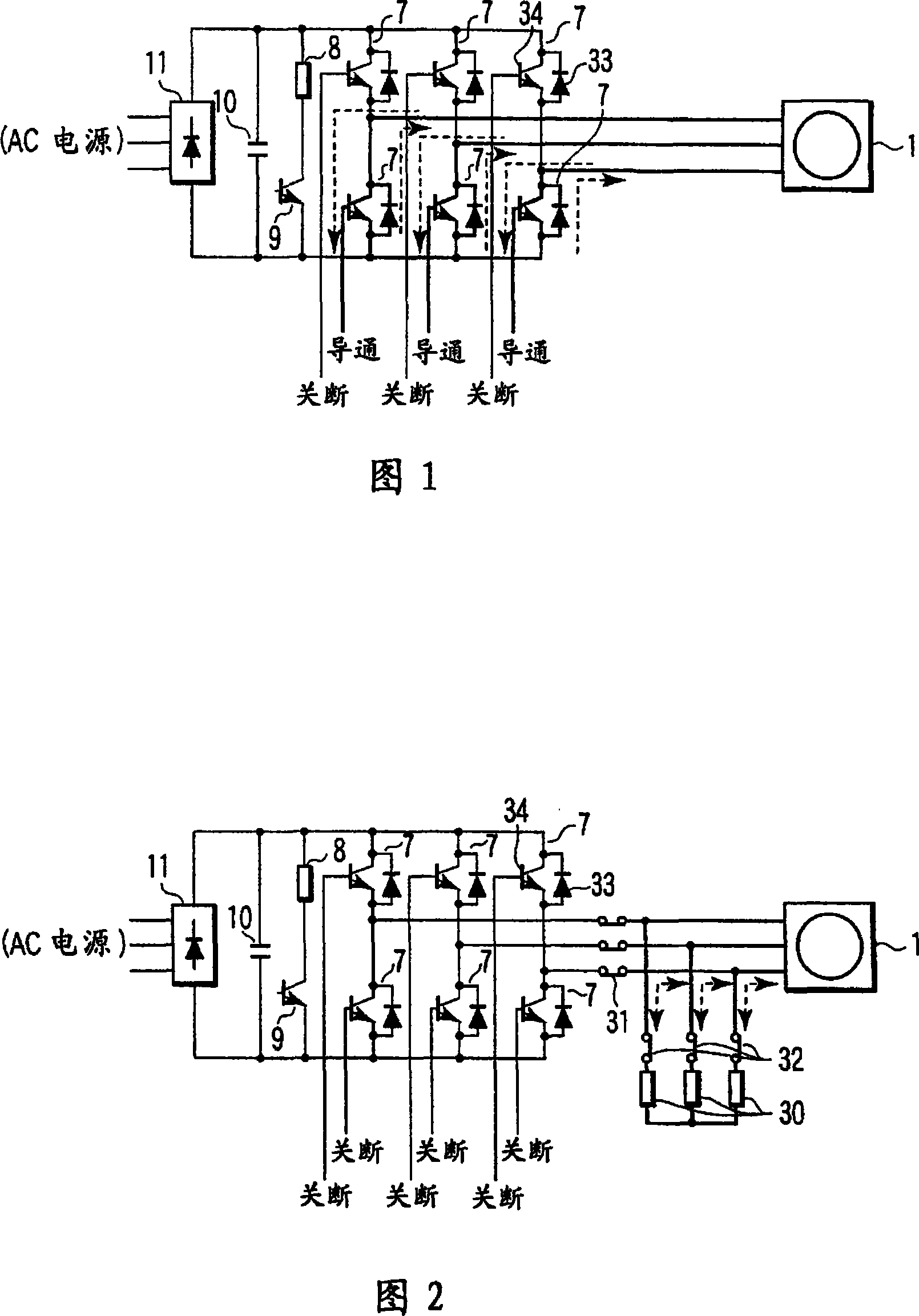
[0023] Dynamic braking will be explained first. Fig. 1 shows a configuration example of dynamic braking of an elevator control apparatus according to a first embodiment of the present invention.

[0024] In the dynamic braking shown in FIG. 1 , the three-phase alternating current supplied from the AC power source is full-wave rectified by the rectifier circuit 11 into direct current. Ripples in the rectified direct current are absorbed by the smoothing capacitor 10, and the direct current is supplied to the inverter circuit. At both ends of the smoothing capacitor 10, a series circuit composed of a damping resistor 8 and a damping resistor energization element 9 is provided.

[0025] In the inverter circuit, six parallel circuits 7 composed of diodes 33 and switching elements 34 are connected in bridge form. By energizing and interrupting each switching element 34 of the inverter circuit with a pulse wi...

Embodiment 2

[0053] A second embodiment of the present invention will be explained. Among the components of the elevator control apparatus according to the following embodiments, the explanation of the same components as those shown in FIG. 1 is omitted. In the operation of the elevator control apparatus according to the following embodiments, operations from the start of normal operation to implantation are almost the same as those explained in the first embodiment, and detailed explanation thereof is omitted.

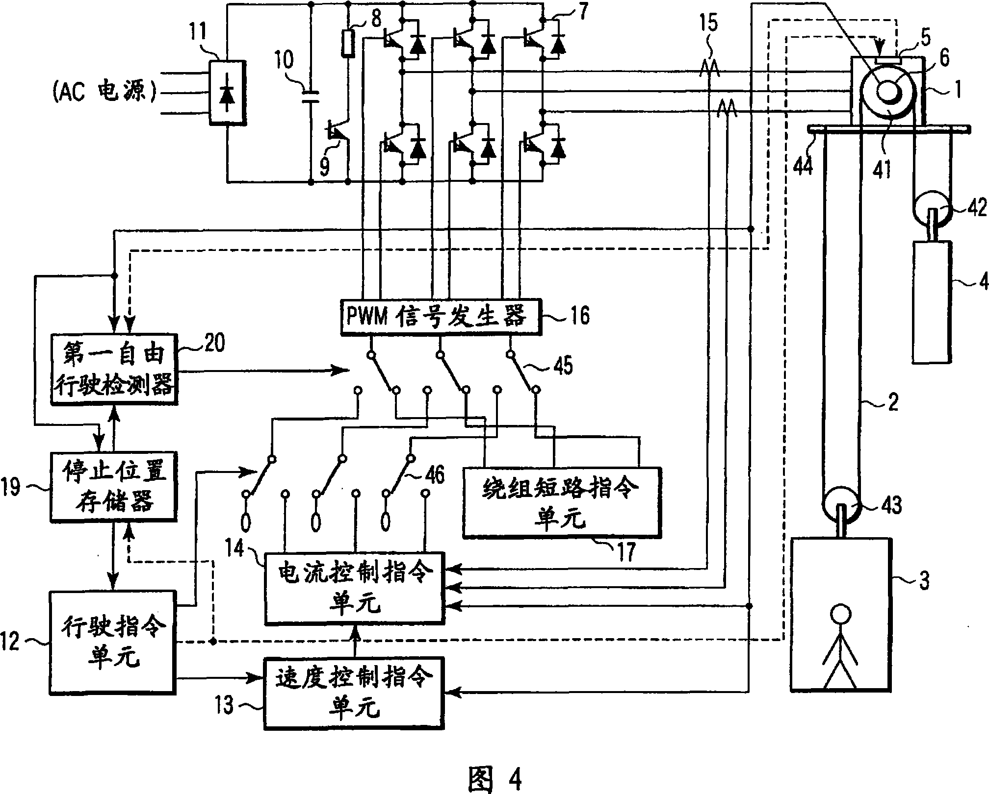
[0054] Fig. 4 shows a configuration example of an elevator control apparatus according to a second embodiment of the present invention.

[0055] As shown in FIG. 4, the elevator control apparatus according to the second embodiment of the present invention has a stop position memory 19 and a first free running detector 20 instead of the braking error detector 18 explained in the first embodiment.

[0056] When running the elevator car 3 , the travel command unit 12 outputs a brake...

Embodiment 3

[0068] A third embodiment of the present invention will be explained. Fig. 5 shows a configuration example of an elevator control apparatus according to a third embodiment of the present invention.

[0069] As shown in FIG. 5, the elevator control apparatus according to the third embodiment of the present invention has a second free running detector 21 instead of the braking error detector 18 explained in the first embodiment.

[0070] When running the elevator car 3 , the travel command unit 12 outputs a brake disconnection signal, and connects the second switch 46 to the current control command unit 14 .

[0071] In addition, the running command unit 12 outputs a brake release signal to the second free running detector 21 . The second free running detector 21 has the function of switching the first switch 45 and connects the first switch 45 to the current control command unit 14 when receiving the brake disconnection signal from the travel command unit 12 .

[0072] When t...


PUM


Abstract

An elevator control apparatus having a rectifier circuit to convert AC power from an AC power supply to DC power, a smoothing capacitor to smooth a ripple of the DC power converted by the rectifier circuit, an inverter which is formed by connecting diodes and switching elements in the form of a bridge, and outputs the smoothed DC power by converting to variable voltage / frequency AC power, an electric motor which moves an elevator up and down car by driving from the AC power output from the inverter, a run control unit which controls energizing / interruption of each switching element of the inverter so that the variable voltage / frequency AC power is output according to a predetermined operation pattern, a brake unit which mechanically brakes movement of the elevator car, a brake control unit which operates the brake unit to stop movement of the elevator car when the elevator car arrives at a floor, an error detector which detects a malfunction of the brake unit when the elevator car arrives at a floor, and a regenerative brake control unit which regeneratively brakes the electric motor by closing the switching elements of one polarity side of the inverter, and opening the switching elements of the other polarity side, when a malfunction of the brake unit is detected by the error detector.

Description

technical field [0001] The present invention relates to an elevator control apparatus which converts alternating current supplied from an AC power source into direct current and further converts direct current into alternating current through an inverter, and supplies direct current to a motor for moving an elevator car up and down. Background technique [0002] In a conventional elevator system installed in a building, a rope having a counterweight and a cage at both ends is suspended on a sieve of a motor provided on an upper side of an up and down passage. Typically, the weight of the counterweight is adjusted to a weight substantially equal to the weight of an elevator car filled to half its load capacity. Therefore, if the elevator car is not loaded to half its capacity, the car and counterweight are out of balance. Therefore, a brake unit is installed to keep the elevator car stationary while stopping the elevator car with no load at each floor and stopping the drivin...

Claims


Application Information

Patent Timeline
Patent Type & Authority Applications(China)
IPC IPC(8): B66B1/00
CPCB66B1/306B66B1/32B66B5/021
Inventor 秋月博光岛根一夫高崎一彦
Owner TOSHIBA ELEVATOR KK
Why Eureka
Try Eureka