Method and device for recycling residual heat of blast furnace low-temperature recirculated water with heat pump technology

A technology of circulating water and blast furnace, which is applied in the field of recycling waste heat of blast furnace circulating water in the process of iron and steel production, to achieve the effect of realizing waste heat recovery

Inactive Publication Date: 2008-03-05
LAIWU IRON & STEEL GRP
View PDF1 Cites 14 Cited by
  • Summary
  • Abstract
  • Description
  • Claims
  • Application Information

AI Technical Summary

Problems solved by technology

[0004] Aiming at the utilization of low-temperature circulating water waste heat in the metallurgical production process, the purpose of the present invention is to provide a method and equipment for recovering the waste heat of blast furnace circulating water. The principle of the present invention is based on the existing blast furnace circulating water system and steam boiler water supply system In addition, add heat pump unit and heat exchange device, use the principle, method and related equipment of heat pump to cool the blast furnace circulating water, preheat the new water of the boiler, replace the heat in the blast furnace circulating water as much as possible, and apply it to the thermoelectric boiler. To the purpose of saving energy and reducing consumption

Method used


Image

  • Method and device for recycling residual heat of blast furnace low-temperature recirculated water with heat pump technology

Examples


Embodiment 1

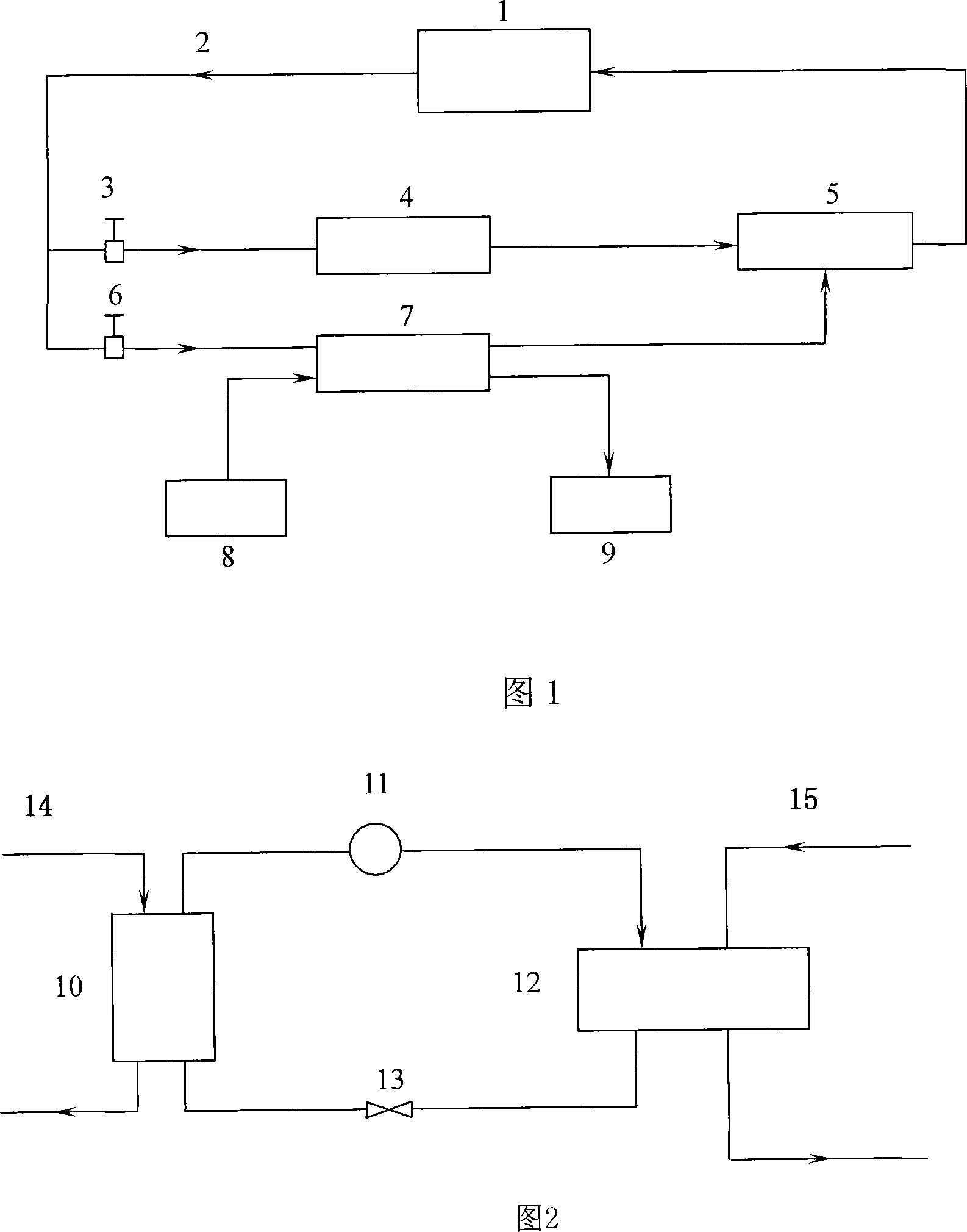
[0029] Equipment for recovering waste heat from blast furnace circulating water, including: heat pump unit 7, cooling tower 4, boiler 9, water absorption pool 5, and two control valves; one inlet of heat pump unit 7 passes through control valve 6 and blast furnace low-temperature circulating water delivery pipe 2 and blast furnace 1 is connected to the outlet, and its outlet is connected to the inlet of the water absorption pool 5 through a pipeline, and the outlet of the water absorption pool 5 is connected to the inlet of the blast furnace 1 through a pipeline; the other inlet of the heat pump unit 7 is connected to the soft water station 8 through a pipeline, and its outlet is connected to the water softening station 8 through a pipeline. It is connected with the boiler 9; the inlet of the cooling tower 4 is connected with the outlet of the blast furnace 1 through the control valve 6 and the blast furnace low-temperature circulating water delivery pipe 2, and the outlet of th...

Embodiment 2

[0038] The method for recovering waste heat from blast furnace circulating water of the present invention will be further described below in conjunction with FIG. 1 .

[0039] As shown in Figure 1, after the blast furnace circulating cooling water passes through the pipeline 2 from the blast furnace 1, it is divided into two paths in consideration of the reliable operation of the system. One path can be controlled by the valve 3 and enter the cooling tower 3 for cooling. Re-enter the blast furnace 1 for recycling, and the other way is controlled by the valve 6, and enters the steam absorption heat pump unit 7. After heat exchange, the circulating water of the blast furnace enters the water absorption pool 5, and then enters the circulation system of the blast furnace 1 for use, while the boiler uses The new water is transported from the soft water station 8 to the heat pump unit 7 through pipelines to absorb heat for preheating, and then enters the steam boiler 8 .

[0040]Fig...


PUM


Abstract

This invention relates to a recovery process and method of waste heat of blast furnace circulating water in the steel production, which installs heat pump unit on the pipeline to recover the waste heat in the of 40-50deg.C with the low-boiling working substance in the heat pump unit, and the cooled blast furnace circulating soft water enters the blast furnace circulating water system directly; the heat exchanger is installed on the water replenishing pipe of the steam boiler to provide the heat in the low-boiling working substance with waste heat and the driving heat of heat pump working to the fresh boiler water in the pipeline network beside the heat exchanger to increase the temperature to 70-80deg.C; the fresh boiler water through the heat exchanger is imported to the boiler system. This invention realizes the recovery of the waste heat in the blast furnace low-temperature circulating water by the installation of heat pump unit and heat exchanger without big alteration and applies the heat on the preheating of the fresh water in the steam boiler to save the needed steam and energy.

Description

technical field [0001] The invention relates to a method and equipment for recovering waste heat of blast furnace circulating water in the process of iron and steel production, in particular to a method and equipment for recovering waste heat of blast furnace circulating water for water preheating of thermoelectric boilers. Background technique [0002] With the increasingly tense energy sources, energy conservation and emission reduction have become important tasks. A large amount of low-temperature waste heat is generated in the process of steel production, especially the waste heat of low-temperature circulating water at 40-80°C. According to statistics, this part of the heat loss accounts for more than 60% of the energy loss in steel production. Due to the low temperature of circulating water, it is difficult to effectively use it. For a long time, this part of energy has basically been dissipated through cooling towers, which not only caused a lot of waste of energy and...

Claims


Application Information

Patent Timeline
IPC IPC(8): F22D1/36
Inventor 孙庆亮董杰吉种振宇刘智伟董晓春李燕青孙进闫志华
Owner LAIWU IRON & STEEL GRP
Why Eureka
Try Eureka