Direct-contact type flue gas waste heat deep recycling and pollution reducing device and method

A flue gas waste heat and contact technology, which is applied in the field of flue gas treatment and waste heat recovery, can solve the problems of acid corrosion service life of flue gas, and achieve the effect of reducing emissions and improving fuel utilization efficiency.

Inactive Publication Date: 2016-09-21
北京华源泰盟节能设备有限公司
View PDF4 Cites 6 Cited by
  • Summary
  • Abstract
  • Description
  • Claims
  • Application Information

AI Technical Summary

Problems solved by technology

[0003] The purpose of this invention is to solve the deep recovery of flue gas waste heat and solve the problems of acid corrosion and service life, and at the same time realize the integration of desulfurization, denitrification and dust removal

Method used


Image

  • Direct-contact type flue gas waste heat deep recycling and pollution reducing device and method
  • Direct-contact type flue gas waste heat deep recycling and pollution reducing device and method

Examples


Embodiment 1

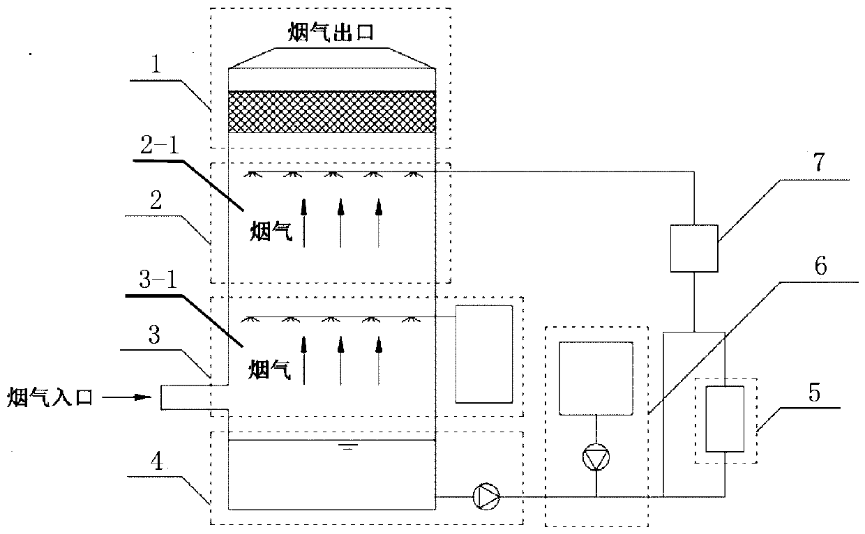
[0021] like figure 1 As shown, a direct contact flue gas waste heat deep recovery and pollution reduction device, the device includes a flue gas treatment subsystem and a waste water treatment subsystem; this equipment is suitable for treating more SO contained in coal-fired flue gas 2 , NOx and soot flue gas.

[0022] The flue gas treatment subsystem includes a flue gas oxidation module 3, a flue gas waste heat depth recovery module 2, and a flue gas demist and dust removal module 1; the flue gas oxidation module 3 includes a second flue gas channel 3-1 and a The oxidant release device in 3-1, the second flue gas channel 3-1 has a flue gas inlet connected to the source of flue gas to be treated; the flue gas waste heat deep recovery module 2 includes the first flue gas channel 2-1 And the residual hot water spraying device and the residual hot water recovery outlet arranged in the first flue gas channel 2-1, the gas outlet of the second flue gas channel 3-1 and the air inlet...

Embodiment 2

[0036] Use the direct contact flue gas waste heat deep recovery and pollution reduction device in Example 1 to carry out flue gas waste heat deep recovery and pollution reduction treatment method: This method is suitable for treating more SO contained in coal-fired flue gas 2 , NOx and soot flue gas.

[0037] Including two parallel workflows of flue gas treatment and waste water circulation,

[0038] Flue gas treatment: the flue gas first enters the flue gas oxidation module 3 for oxidation treatment; the oxidized flue gas enters the flue gas waste heat deep recovery module 2 and directly contacts the low-temperature waste water sprayed by the waste water spraying device to release heat for heating At the same time, the water-soluble pollutants and part of the smoke in the flue gas are absorbed by the residual hot water; the flue gas passes through the flue gas waste heat depth recovery module 2 and then enters the flue gas demisting and dust removal module 1 to remove the car...

Embodiment 3

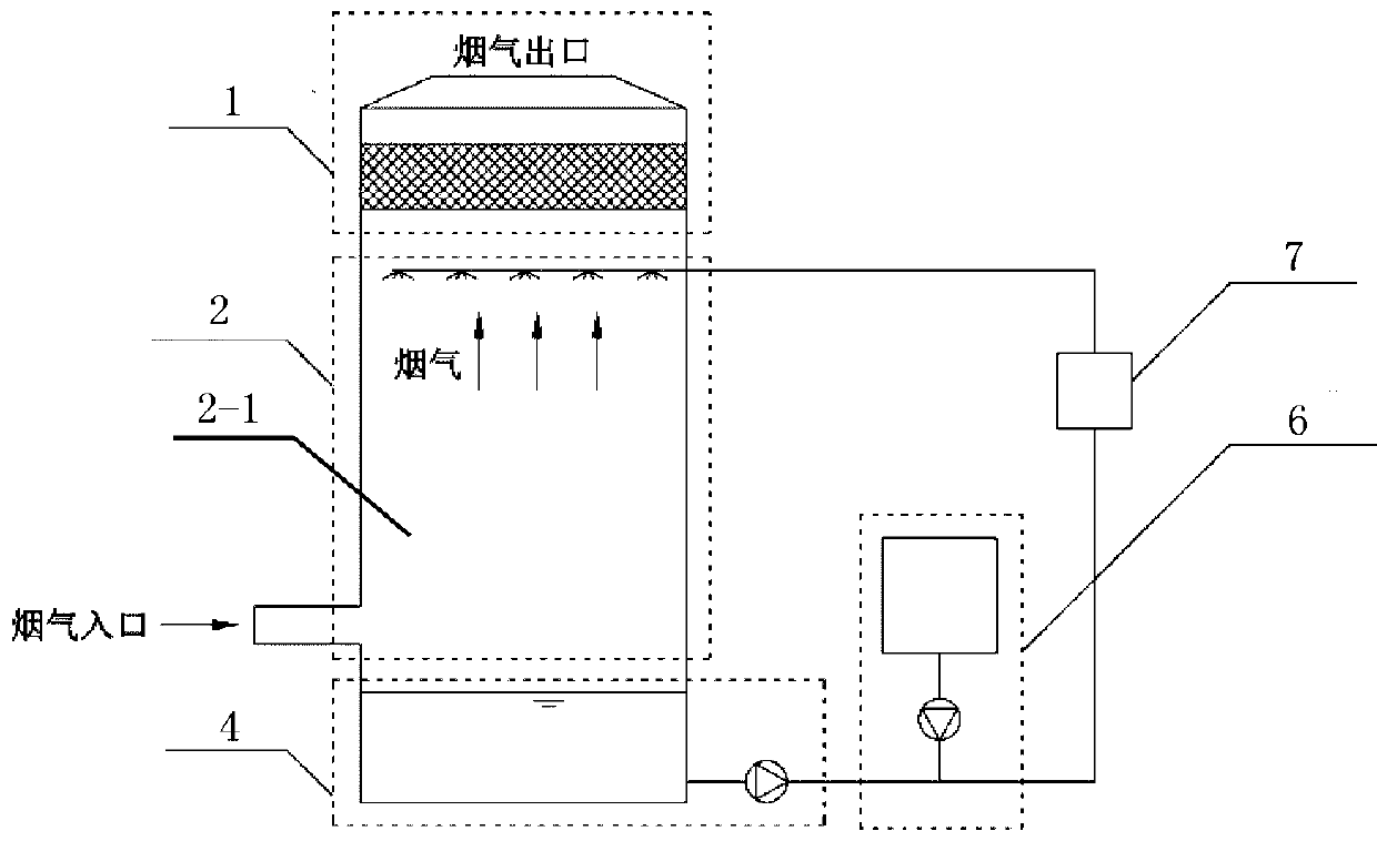
[0046] like figure 2 As shown, a direct contact flue gas waste heat depth recovery and pollution reduction device, the device includes a flue gas treatment subsystem and a waste water treatment subsystem;

[0047] The flue gas treatment subsystem includes a flue gas waste heat deep recovery module 2 and a flue gas demist and dust removal module 1; the flue gas waste heat deep recovery module 2 includes a first flue gas channel 2-1 and a The residual hot water spraying device and residual hot water recovery outlet in 2-1, the first flue gas channel 2-1 is provided with a flue gas inlet connected to the source of flue gas to be treated, and the gas outlet of the first flue gas channel 2-1 Connect the air inlet of the smoke demist and dust removal module 1, and the smoke demist and dust removal module 1 is provided with a smoke outlet connected to the atmosphere;

[0048] The waste water treatment subsystem includes waste water circulation module 4, waste water desulfurization ...


PUM


Abstract

The invention relates to a direct-contact type flue gas waste heat deep recycling and pollution reducing device and method. The device comprises a flue gas treatment subsystem and a waste heat water treatment subsystem. The flue gas treatment subsystem comprises a flue gas oxidation module, a flue gas waste heat deep recycling module and a flue gas mist removing and dust removing module. The waste heat water treatment subsystem comprises a waste heat water circulating module, a waste heat water desulfurization and denitrification module and a waste heat water dust removing module. By means of the direct-contact type flue gas waste heat deep recycling and pollution reducing device, heat exchange between flue gas and low-temperature waste heat water is achieved, the flue gas discharging temperature is decreased to be the dew point temperature or lower, the flue gas low-temperature heat is recycled, the flue gas is subjected to desulfurization, denitrification and dust removal treatment, and emitted flue gas pollutants are reduced. According to the direct-contact type flue gas waste heat deep recycling and pollution reducing device and method, the problem of corrosion to equipment by flue gas condensate is solved, the recycled heat can be used for various low-temperature heat users, the utilization efficiency of fuel can be effectively improved, and secondary treatment on the flue gas can be achieved.

Description

technical field [0001] The invention belongs to the field of flue gas treatment and waste heat recovery, and in particular relates to a direct contact flue gas waste heat deep recovery and pollution reduction device and method which utilizes low-temperature waste hot water to exchange heat with flue gas and reduce pollutant concentration. Background technique [0002] With the development of waste heat recovery technology, the low-temperature waste heat of flue gas has become one of the concerns of people. Conventional flue gas waste heat recovery technology generally uses partition wall heat exchangers such as economizers, air preheaters, and economizers to recover high-temperature flue gas; if the exhaust gas temperature is further reduced to recover waste heat, due to the condensation of acidic substances in the flue gas, Problems such as steam condensation will cause serious corrosion to the partition wall heat exchanger, greatly affecting the service life and economy of...

Claims


Application Information

Patent Timeline
Patent Type & Authority Applications(China)
IPC IPC(8): B01D53/60B01D53/78B01D53/76B01D53/40B01D47/06B01D50/00
CPCB01D47/06B01D53/14B01D53/1493B01D53/18B01D53/40B01D53/60B01D53/76B01D53/78B01D2258/0283B01D2247/101B01D2247/10B01D2251/10B01D2247/107B01D2252/103B01D50/60Y02P70/10
Inventor 王钦波杨巍巍肖常磊冯恩泉姚颖唐海涛
Owner 北京华源泰盟节能设备有限公司
Why Eureka
Try Eureka