Stainless steel plate integral burner

A stainless steel plate and burner technology, applied in the direction of gas fuel burners, burners, combustion methods, etc., can solve the problems of complex structure, increased cost, and many production processes, and achieve simple manufacturing process, avoid deformation and damage, and fix strength high effect

Inactive Publication Date: 2008-03-26
北京合百意生态能源科技开发有限公司
View PDF2 Cites 5 Cited by
  • Summary
  • Abstract
  • Description
  • Claims
  • Application Information

AI Technical Summary

Problems solved by technology

[0002] At present, among the burners used in gas stoves, many still use cast iron burners covered with cast copper fire dividers. The burner burners produced by the casting method are too heavy, and the inner cavity is easy to rust, which is inconvenient in storage and transportation. , the shape of the burner is not beautiful
In addition, the casting production process is very easy to produce environmental pollution. In addition, the price of the fire distributor made of cast copper is high, so the cost of the entire burner is high and it is not practical. It needs to be improved.
[0003] At present, there are also gas stove burners made of stainless steel plates. First, the main fire part is made of stainless steel plates, and the number of parts is large, which increases the cost.
Second, the central small fire is manufactured separately, and then assembled with the main fire part, which increases the processing procedure and cost
Third, the structure is relatively complicated, which is not conducive to production and assembly
The stainless steel combustible burner disclosed in Chinese Patent Application No. 92241052.6 has the above-mentioned defects. There are many burner parts, many production processes, high cost, and it is not conducive to assembly. It is necessary to improve
Chinese Patent Application No. 200620051927.9 discloses the integral burner of the stainless steel plate of the gas stove, and the air inlets of the main fire and the central fire injection pipe are not on the same horizontal plane but on the same vertical plane, which requires a special valve body to match it. , it also increases the cost from another aspect, and it is necessary to improve

Method used


Image

  • Stainless steel plate integral burner
  • Stainless steel plate integral burner

Examples


Embodiment Construction

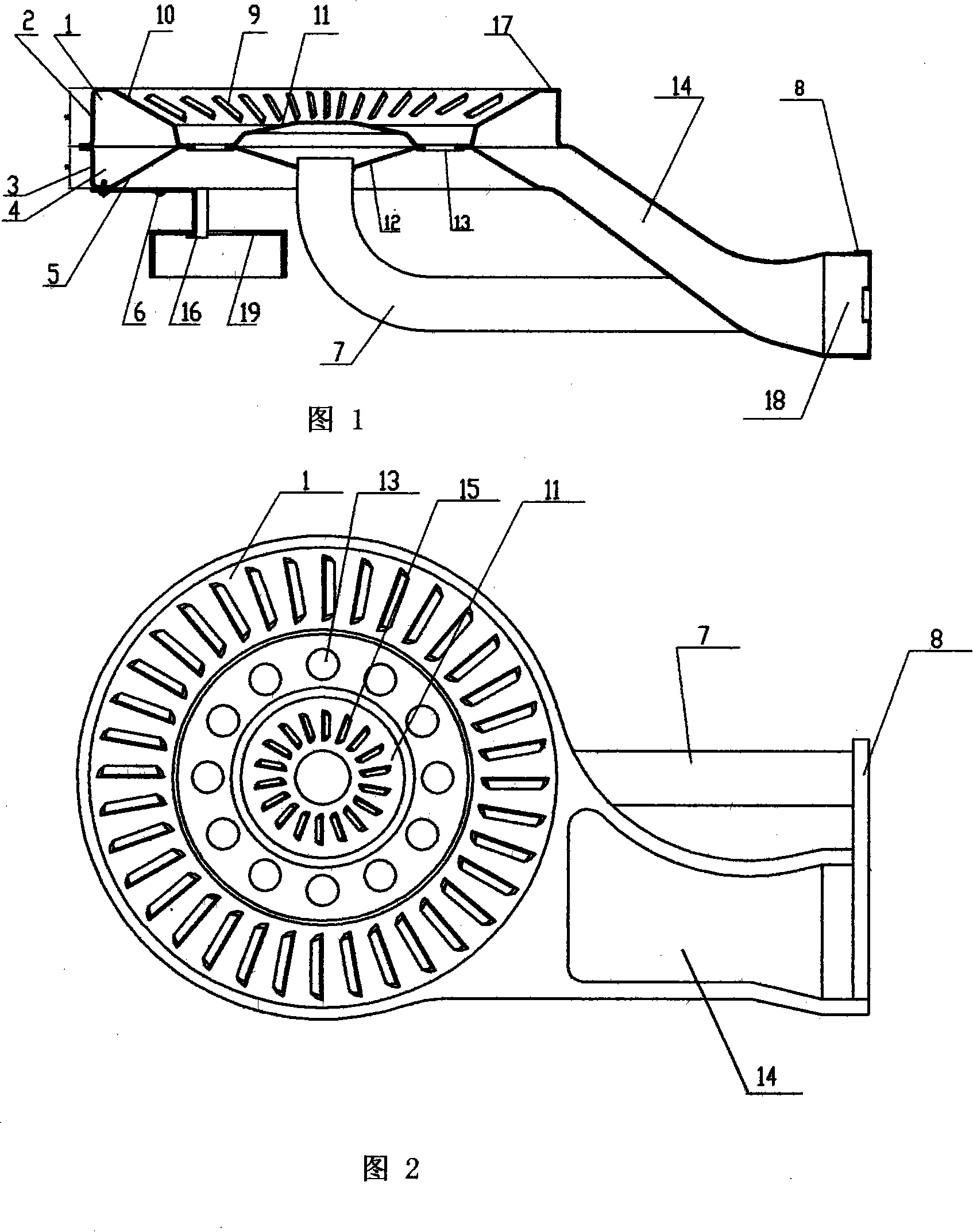
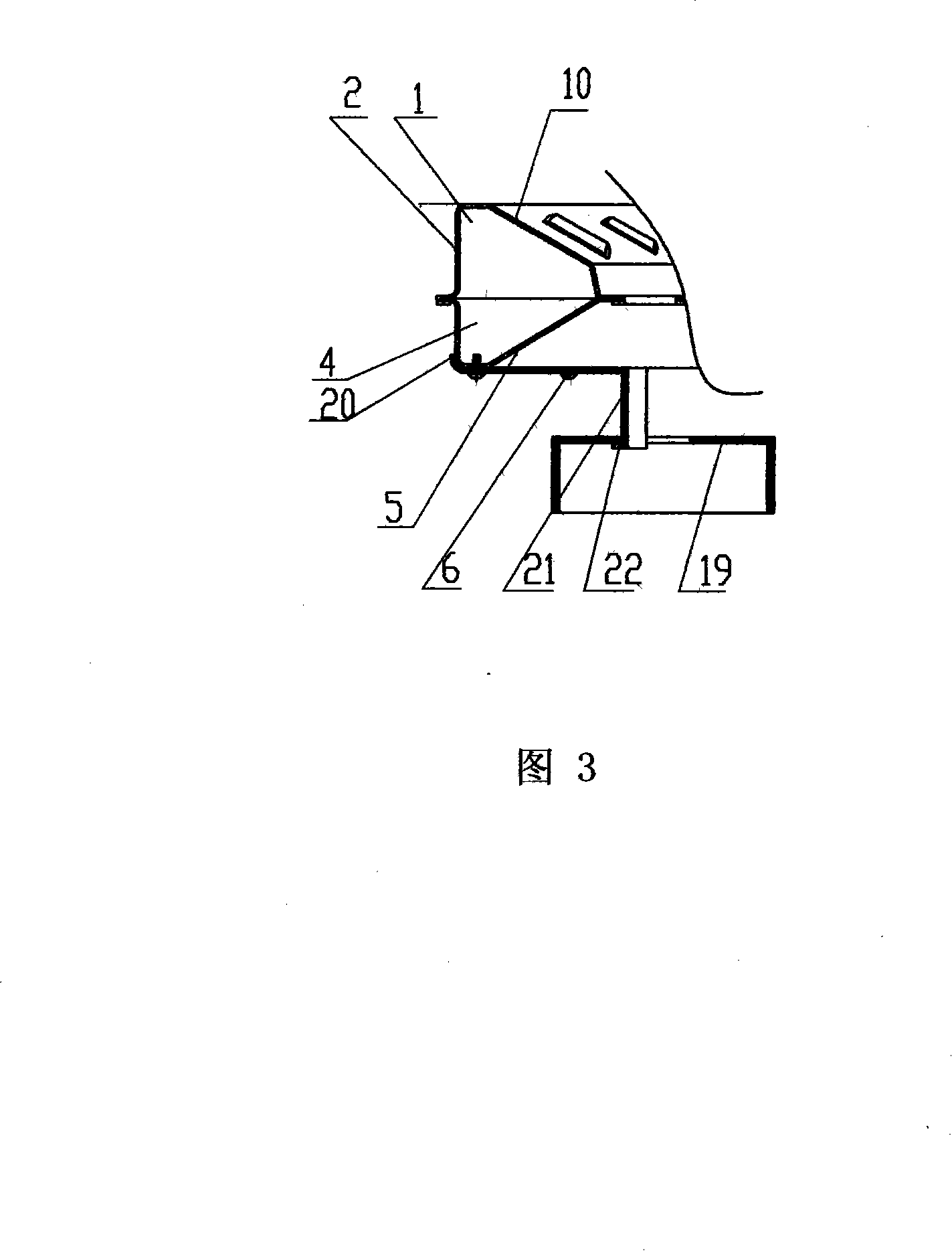
[0020] The specific implementation of the present invention will be further described below in conjunction with the embodiments given in the drawings.

[0021] As shown in Figures 1 and 2, the stainless steel plate integral burner according to the present invention includes a burner upper body 1 and a burner lower body 4, a main fire ejection tube 14, a central small fire ejection tube 7, and a burner upper body There is a convex cone-shaped conical ring with a long slit fire hole 9 on it, which is characterized in that the burner upper body 1 is a stamped and formed piece of stainless steel plate, and the outer ring has a long arc-shaped slit fire hole 9 The conical disc portion 10, the upper boss-shaped portion 11 with a long slit fire hole 15 in the center, and the annular transition portion with a vent 13 between the two, and the main lead extending from the conical disc portion The upper cover of the shoot tube 14, the riveted edge riveted with the lower body 4 of the burner,...


PUM


Abstract

This invention relates to cooking utensils technology field, especially a stainless steel plate integral combustor. It includes combustor superior body, combustor inferior body, main flame jet pipe, center small flame jet pipe. The combustor superior and inferior bodies are pressed into sections, which includes peripheral conical plate shaped part, center projection shaped part, transition part with air holes and riveting rim riveted by main jet pipe superior and inferior covers and combustor superior and inferior bodies. The center has fuel gas inlet hole, which is communicated to the center small flame jet pipe. The entries of main flame jet pipe and center small flame jet pipe are at the same plane. They are connected by fixed air adjusting plate which rivets with a valve body nozzle. The center fuel gas inlet hole of combustor inferior body and center small jet pipe are plugged connected. The combustor inferior body is arranged with combustor fixing support that is fixed on the bottom of combustor inferior body by self-tapping screw. This invention is simple and convenient.

Description

Technical field [0001] The invention relates to the technical field of cooking utensils, in particular to a stainless steel plate integral burner. Background technique [0002] Among the burners currently used in gas stoves, there are many flame splitters that still use cast iron burners and cast copper materials. The burner burners produced by the casting method are too heavy and the inner cavity is easy to rust, and it is inconvenient for storage and transportation. , The appearance of the burner is not beautiful. In addition, environmental pollution is easily generated during the casting production process. In addition, the price of the cast copper fire splitter is high, so the entire burner is expensive and impractical, and needs to be improved. [0003] At present, there are also gas stove burners made of stainless steel plates. First, the main fire part is made of stainless steel plates, and the number of parts is large, which increases the cost. The second is that the cent...

Claims


Application Information

Patent Timeline
Patent Type & Authority Applications(China)
IPC IPC(8): F23D14/00
Inventor 颜开
Owner 北京合百意生态能源科技开发有限公司
Why Eureka
Try Eureka