
Multi-relative position electrohydraulic scale servo system position control method

A technology of servo system and electro-hydraulic ratio, which is applied in manufacturing tools, presses, etc., can solve the problems of low precision of position control, non-adjustment of liquid flow, and temperature rise of hydraulic oil.

Inactive Publication Date: 2008-04-02
CENT SOUTH UNIV
View PDF0 Cites 6 Cited by
  • Summary
  • Abstract
  • Description
  • Claims
  • Application Information

AI Technical Summary

Problems solved by technology

At present, the control system of the large-scale die forging hydraulic press distributor adopts the on-off valve control system of the logic cone valve to control the direction of the liquid flow, but does not adjust the size of the liquid flow, resulting in low position control accuracy and poor reliability of the hydraulic press distributor control system. , system vibration and hydraulic oil temperature rise are serious

Method used


Image

  • Multi-relative position electrohydraulic scale servo system position control method
  • Multi-relative position electrohydraulic scale servo system position control method
  • Multi-relative position electrohydraulic scale servo system position control method

Examples


Embodiment approach

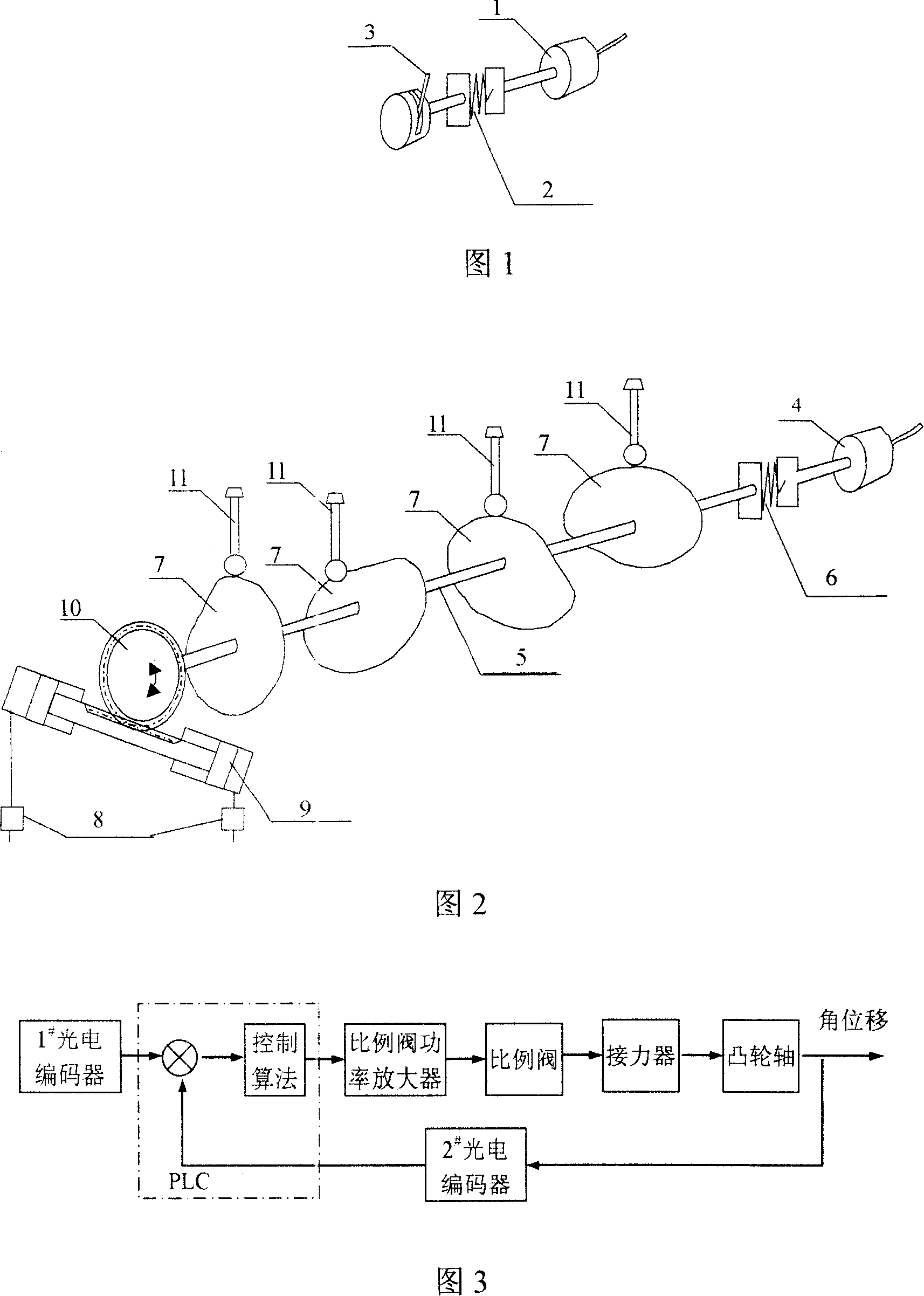
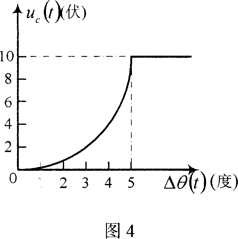
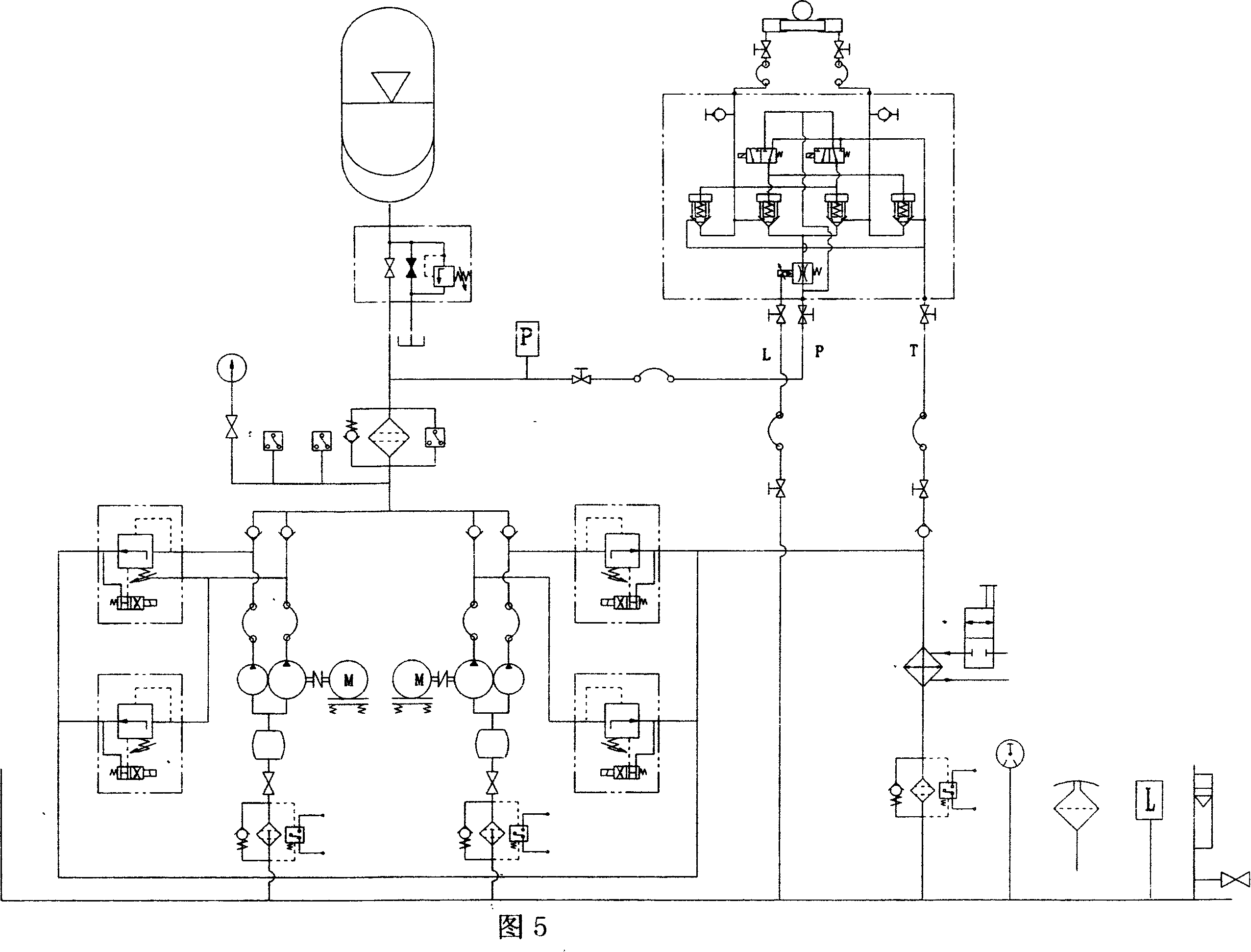
[0012] [Implementation mode] As shown in Figure 1 and 2, 1 # The photoelectric encoder 1 is connected with the rotating shaft of the operating handle 3 through an elastic coupling 2 . 2 # The photoelectric encoder 4 is installed on one end of the distributor shaft 5 and is connected with the distributor rotating shaft 5 through an elastic coupling 6 . Multiple cams 7 are installed on the distributor shaft 5. The relative position of each cam depends on the needs of multiple working conditions of the system and is related to the angle of the shaft. The rotation angle of the cam shaft is controlled by a digital electro-hydraulic proportional servo system 8. The hydraulic oil flow rate and the moving speed of the hydraulic cylinder piston rod 9 are described by the following formula:

[0013] Q=k·V

[0014] In the above formula, Q is the hydraulic oil flow rate, k is the proportional coefficient, and V is the moving speed of the hydraulic piston rod 9 . Controlling the hydrau...


PUM


Abstract

A multi associated location electro hydraulic proportional servo system positioning controlling method uses flow proportional valve, so that the rate flowing into the fuel tank is adjusted according to the angle deviation of a camshaft, which overcomes the camshaft displacement frequently moving near the set value and the system vibration resulted by the moving in a former switch valve servo system. Oil source uses double-vane pump and control the working state of two sub-pumps according to specific condition, which reduces the overflow losses of system overflow valve to the largest extent. The present invention improves the system working efficiency, fundamentally resolves the problem of high oil temperature seriously affecting system working reliability in former system and improves the precision of large-scale forging hydraulic distributing machine position controlling system.

Description

[technical field] [0001] The invention relates to a control method of a large die forging hydraulic press, in particular to a method for controlling the position of a camshaft of a distributor of a large die forging hydraulic press. [Background technique] [0002] Large die forging hydraulic press is an important large-scale mechanical equipment in the machinery manufacturing industry, which is used for forging high-strength aluminum alloy forgings or complex forgings with holes. The die forging process is completed by the movable parts such as the movable beam, the left and right horizontal beams, the movable worktable, the middle ejector and the side ejector in order. The movement speed and stroke of each part are realized by controlling the rotation angle of each distributor by the digital electro-hydraulic servo system in the way of "oil control water". A set of cams are installed on the shaft of the distributor. The shapes and installation positions of the cams are dif...

Claims


Application Information

Patent Timeline
Patent Type & Authority Applications(China)
IPC IPC(8): B30B15/14B30B15/16
Inventor 喻寿益桂卫华张友旺贺建军阳春华谢永芳王雅琳胡卫华
Owner CENT SOUTH UNIV
Learn More