
Alignment apparatus, alignment method and imagery quality detecting method

A technology for alignment devices and detectors, which is applied to exposure devices, optics, instruments, etc. in photolithography, and can solve the problems of high manufacturing and configuration precision requirements for mirrors and lenses, high energy requirements for alignment lighting sources, and alignment device structures. Complicated problems, to achieve the effect of improving system work efficiency, reducing motion stroke, and optimizing alignment efficiency

Inactive Publication Date: 2008-04-09
SHANGHAI MICRO ELECTRONICS EQUIP (GRP) CO LTD
View PDF1 Cites 43 Cited by
  • Summary
  • Abstract
  • Description
  • Claims
  • Application Information

AI Technical Summary

Problems solved by technology

[0007] The structure of the above-mentioned alignment device is complex, and the alignment beam enters the detector after multiple diffractions and reflections. The energy consumption of the beam is large, and the energy requirements for the alignment illumination source are high; High accuracy requirements for lens manufacturing and configuration

Method used


Image

  • Alignment apparatus, alignment method and imagery quality detecting method
  • Alignment apparatus, alignment method and imagery quality detecting method
  • Alignment apparatus, alignment method and imagery quality detecting method

Examples


Embodiment Construction

[0050] The specific embodiments of the present invention will be further described below in conjunction with the accompanying drawings.

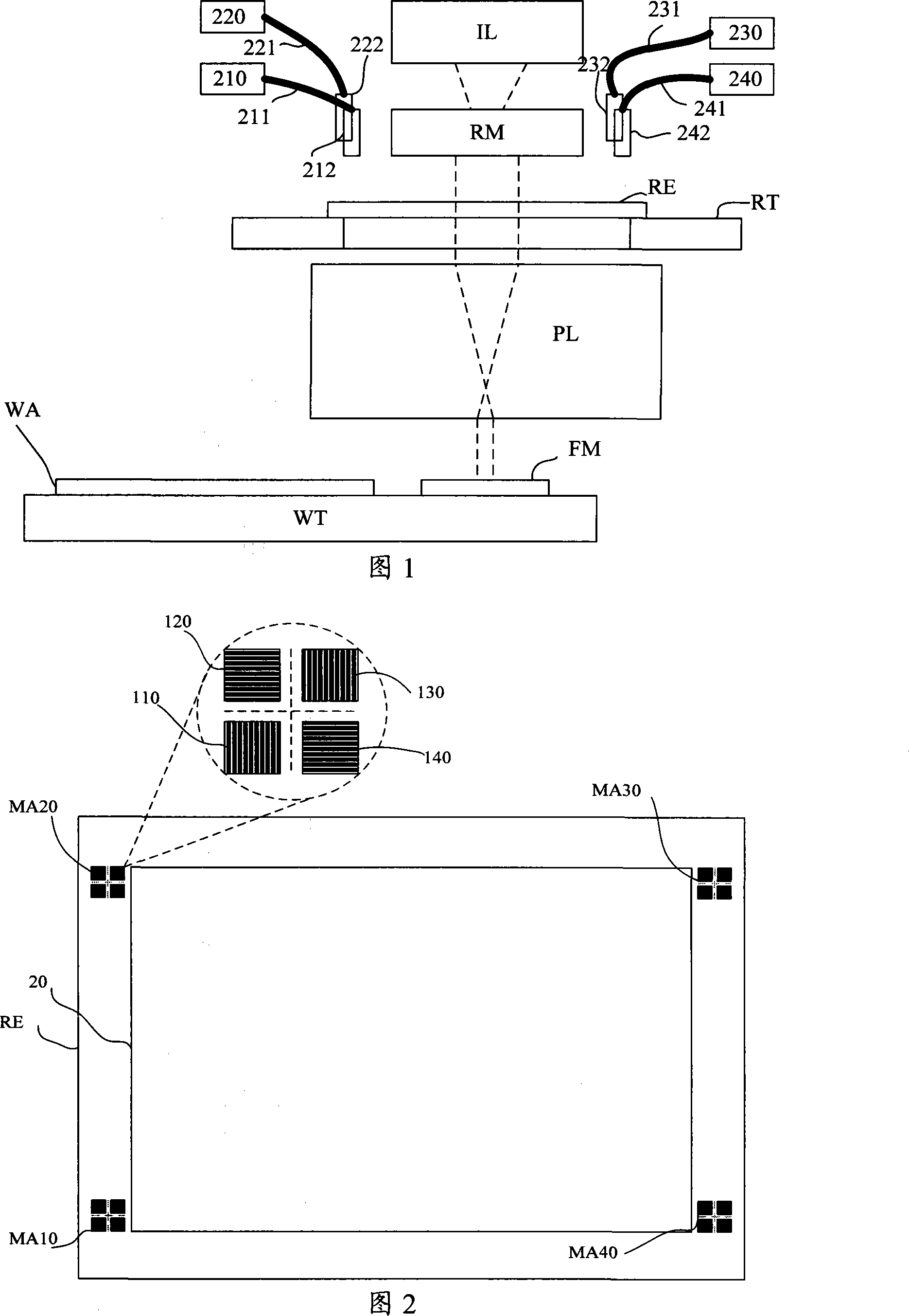
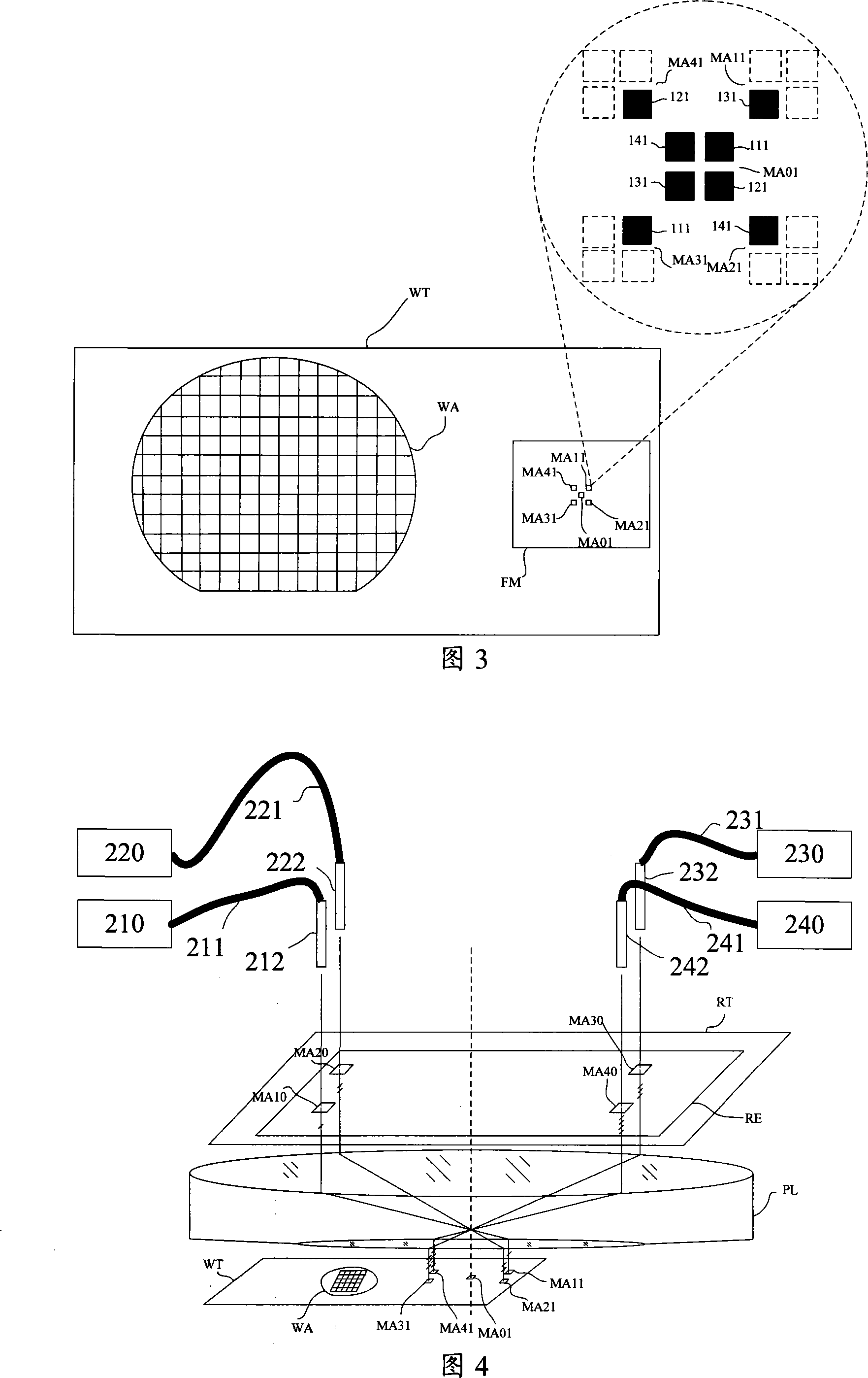
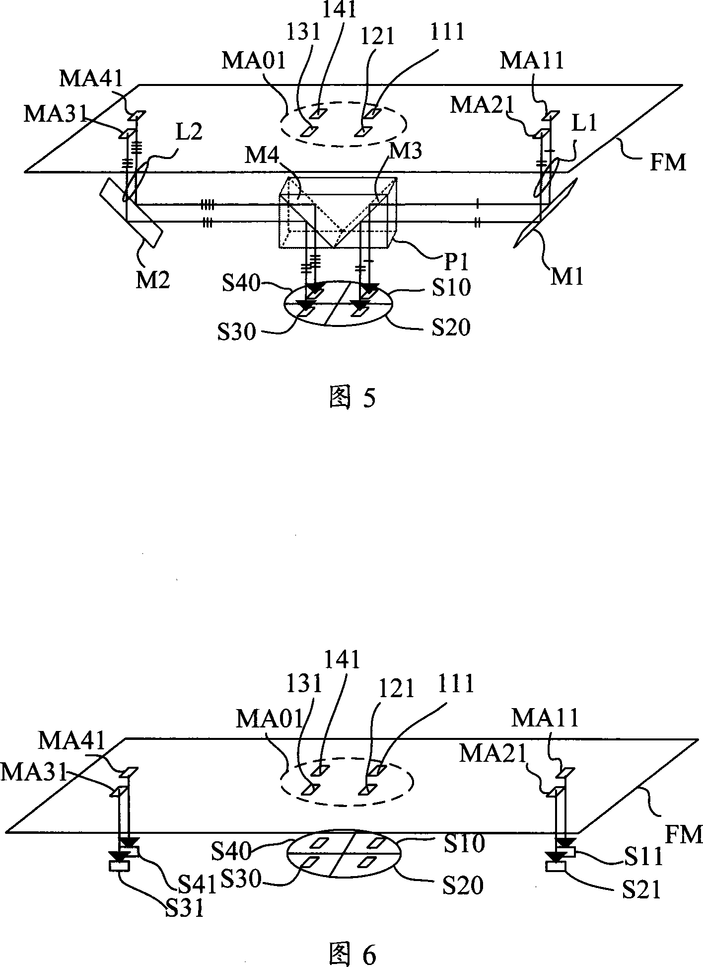
[0051] Figure 1 shows a schematic structural diagram of the alignment system of a lithography machine for mask and reference plate alignment, the alignment system includes an alignment light source and illumination system, mask RE, mask table RT, projection objective lens PL and settings The reference plate FM and the substrate WA on the workpiece table, the mask and the reference plate are respectively placed on both sides of the projection objective lens PL, the mask table can drive the mask to move, and the workpiece table can drive the reference plate and silicon wafer to move, aligning the lighting system It is located above the mask mark and is used to illuminate the mask mark. The alignment illumination light emitted by the alignment illumination system has a wavelength of 633nm or its wavelength is the same as that of the exposure lig...


PUM


Abstract

The present invention discloses an alignment device for alignment between a mask and a working table of a lithography machine, and can determine a basic alignment position by one time alignment with at least four marks. Compared with the prior art, the motion process required by the alignment of the mark is further reduced, thus further reducing the time cost of the alignment and improving the working efficiency of the system. Meanwhile, the present invention has a plurality of ways for processing alignment signals, can obtain different alignment accuracy, and can combine the further optimization of two aspects of the alignment accuracy and alignment efficiency by the selection of different processing strategies for the alignment signals based on the needs of users, and the detection of image quality can be realized.

Description

technical field [0001] The invention relates to an alignment device and an alignment method for a lithography machine, in particular to an alignment device and an alignment method for aligning a mask and a workpiece table in a lithography machine. Background technique [0002] The photolithography apparatus in the prior art is mainly used in the manufacture of integrated circuits (ICs) or other micro devices. With a photolithographic apparatus, multilayer masks with different mask patterns are sequentially imaged in precise alignment on a photoresist-coated wafer, such as a semiconductor wafer or an LCD panel. Lithography devices are generally divided into two categories, one is a stepping lithography device, the mask pattern is exposed and imaged on one exposure area of ​​the wafer, and then the wafer moves relative to the mask to move the next exposure area to the mask pattern and under the projection objective, the mask pattern is again exposed on another exposed area of...

Claims


Application Information

Patent Timeline
IPC IPC(8): G03F7/20G03F9/00
Inventor 韦学志
Owner SHANGHAI MICRO ELECTRONICS EQUIP (GRP) CO LTD
Learn More