Hydrogen gas system for enhancing fuel battery service life

A fuel cell and operating life technology, which is applied in the field of hydrogen systems, can solve the problems of reducing the service life of proton exchange membrane fuel cells, leakage of the hydrogen cavity and hydrogen pipeline of the battery, and easy burning of membrane electrodes, so as to achieve a simple structure and improve the service life. , the effect of wide applicability

Active Publication Date: 2008-04-16
SUNRISE POWER CO LTD
View PDF0 Cites 17 Cited by
  • Summary
  • Abstract
  • Description
  • Claims
  • Application Information

AI Technical Summary

Problems solved by technology

[0005] 1. When the proton exchange membrane fuel cell engine is shut down for a long time, due to the inevitable slight leakage of the battery hydrogen cavity and the hydrogen pipeline, the air enters the battery hydrogen cavity, and under the action of the catalyst on the battery membrane electrode (MEA) , the residual hydrogen in the hydrogen chamber reacts electrochemically with the oxygen in the air, which instantly generates a higher potential, which easily burns the membrane electrode (MEA) and reduces the service life of the proton exchange membrane fuel cell
[0006] 2. When the proton exchange membrane fuel cell engine is turned on and fed with hydrogen, under the action of the catalyst on the battery membrane electrode (MEA), the hydrogen first electrochemically reacts with the oxygen in the air leaked into the hydrogen chamber, and a high potential, easy to burn the membrane electrode (MEA)
[0007] 3. For the newly assembled proton exchange membrane fuel cell engine, due to the natural existence of a large amount of air in the pipeline, hydrogen circuit components and battery hydrogen chamber, electrochemical reactions in the hydrogen chamber are more likely to occur when starting up, and a higher potential is generated instantaneously, reducing the proton Service life of exchange membrane fuel cells

Method used


Image

  • Hydrogen gas system for enhancing fuel battery service life
  • Hydrogen gas system for enhancing fuel battery service life

Examples


Embodiment Construction

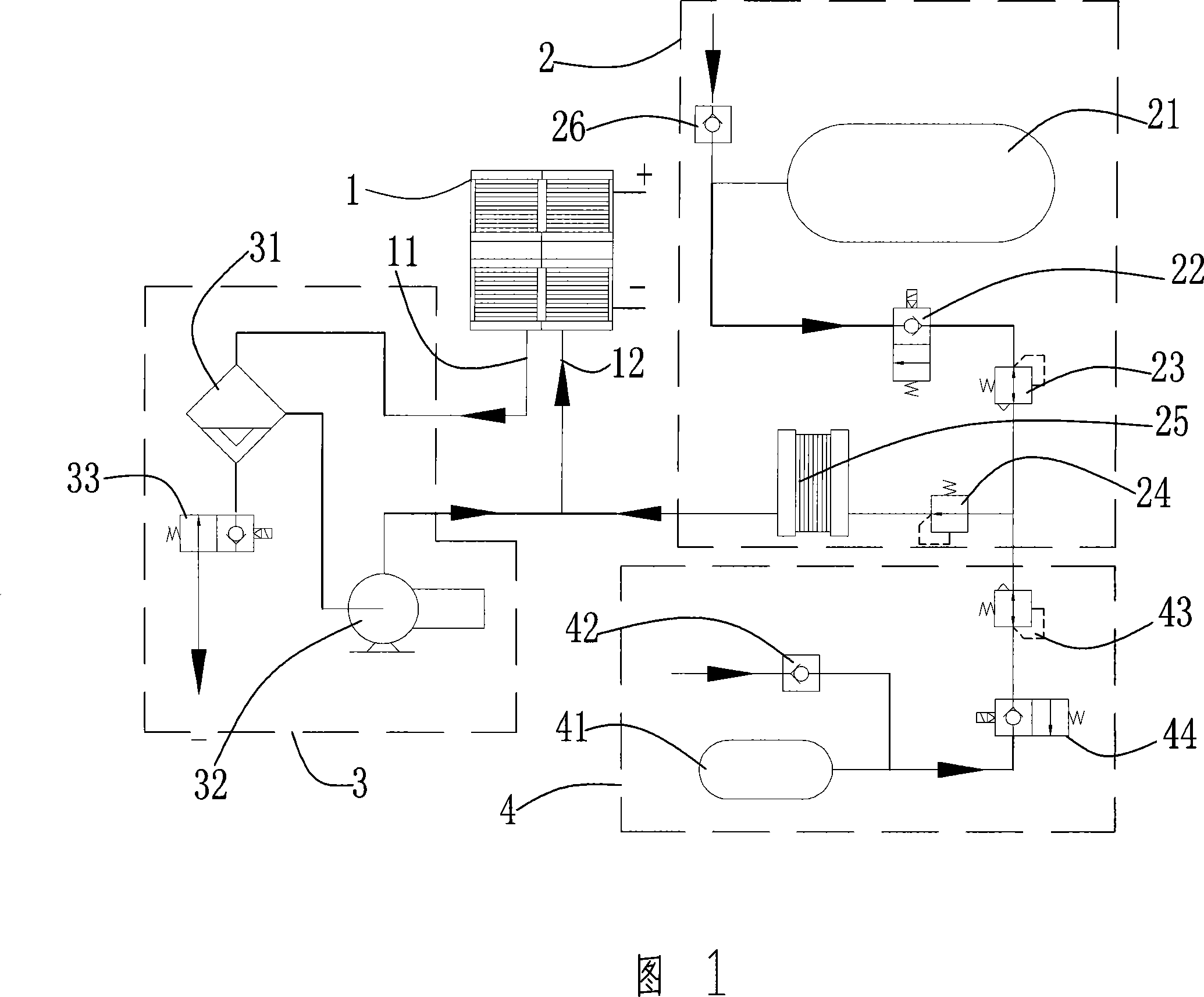
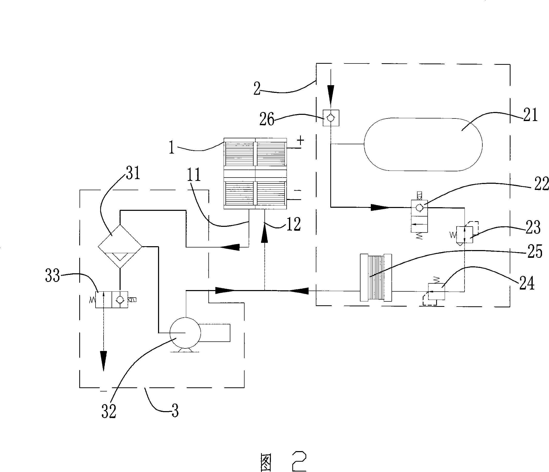
[0028] The present invention will be further described below in conjunction with the embodiment of accompanying drawing 1.

[0029] The hydrogen system includes a fuel cell stack 1 , a hydrogen supply part 2 , a hydrogen return part 3 and a hydrogen purge part 4 . The fuel cell stack 1 is provided with a hydrogen gas inlet 12 and a hydrogen gas outlet 11 . The hydrogen supply part 2 includes a control solenoid valve 22 sequentially connected with a high-pressure hydrogen cylinder 21, a decompression device 23, a voltage stabilizing device 24, a hydrogen humidifying device 25 and a check valve 26 connected to the high-pressure hydrogen cylinder. The outlet of the humidifying device is connected with the hydrogen inlet 12 of the fuel cell stack 1 . The hydrogen return part 3 includes a hydrogen water separator 31 connected to the hydrogen outlet of the fuel cell stack, a hydrogen return pump 32 connected to the hydrogen water separator, and a tail exhaust solenoid valve 33 . T...


PUM


Abstract

A hydrogen system for improving the operational life of a fuel cell comprises a fuel cell stack (1), a hydrogen supply part (2) and a hydrogen reflux part (3), and is characterized by also comprising a hydrogen purging part (4) which consists of a high-pressure purging gas cylinder (41) with purging gas, a purging gas control electromagnetic valve (44) connected with the purging gas cylinder, a reducing valve (43) communicated with the purging gas control electromagnetic valve (44) and a one way valve (42) connected with the purging gas cylinder (41). The residual hydrogen on the hydrogen chamber and the hydrogen channel of the fuel cell stack is removed through purging by the hydrogen purging part; the hydrogen chamber of the fuel cell membrane electrode can be effectively prevented from generating higher instant electric potential by electrochemical reactions to burn the membrane electrode when the system starts up or shuts down, thereby greatly improving the life-span of proton exchange membrane fuel cell. The invention is also characterized by simple structure, high efficiency and long life-span.

Description

technical field [0001] The invention relates to a proton exchange membrane fuel cell, in particular to a hydrogen system of the proton exchange membrane fuel cell. Background technique [0002] Proton exchange membrane fuel cell can be used as a power plant for cars and boats. The working mode of an engine powered by a proton exchange membrane fuel cell is similar to that of an internal combustion engine. It must continuously feed hydrogen fuel and oxidant into the battery, and continuously discharge reaction product water and certain waste heat to maintain the balance of battery materials and heat. Therefore, in order to maintain the continuous operation of the proton exchange membrane fuel cell engine system, it usually includes an air system, a hydrogen system and a cooling part. The air system provides air with certain pressure, humidity and temperature to the fuel cell to ensure the supply of oxidant; the hydrogen system provides hydrogen with corresponding pressure, h...

Claims


Application Information

Patent Timeline
Patent Type & Authority Applications(China)
IPC IPC(8): H01M8/02H01M8/04H01M8/10H01M8/24H01M8/04225H01M8/04228H01M8/1007H01M8/2457
CPCY02E60/521Y02E60/50
Inventor 孙茂喜侯中军王宇晨
Owner SUNRISE POWER CO LTD
Why Eureka
Try Eureka