Domestic garbage landfilling and processing technique with in-situ denitrogenation function and bioreactor

A bioreactor and domestic waste technology, which is applied in the direction of biological sludge treatment, sludge treatment, solid waste removal, etc., can solve the problems of high ammonia nitrogen concentration and achieve high treatment efficiency and low investment and operation costs

Active Publication Date: 2010-05-26
ZHEJIANG UNIV
View PDF6 Cites 2 Cited by
  • Summary
  • Abstract
  • Description
  • Claims
  • Application Information

AI Technical Summary

Problems solved by technology

[0004] The invention provides a domestic waste landfill treatment technology to solve the outstanding problem of excessively high ammonia nitrogen concentration in landfill leachate and realize the organic combination of biological decarburization and biological in-situ denitrification

Method used


Image

  • Domestic garbage landfilling and processing technique with in-situ denitrogenation function and bioreactor
  • Domestic garbage landfilling and processing technique with in-situ denitrogenation function and bioreactor

Examples


Embodiment Construction

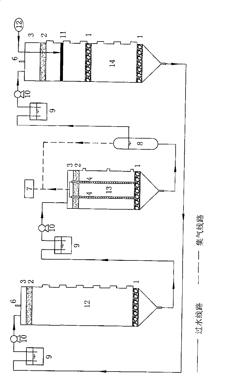
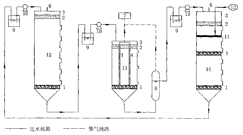
[0015] Such as figure 1 As shown, a domestic waste landfill bioreactor with in-situ denitrification function is composed of a three-stage reactor followed by a fresh landfill 12, a methanogenic reactor 13 and a nitrification reactor 14 through the previous stage of reaction. The leachate outlet at the bottom of the reactor is connected to the top leachate water inlet of the last stage reactor through a water collection bottle 9 and a water inlet pump 10. The reactors at all levels are equipped with garbage chambers and air chambers 3. The chamber 3 is provided with an air duct 6 to facilitate the collection and utilization of landfill gas.

[0016] The bottom of the garbage chamber of the reactors at all levels is covered with a gravel layer 1 to facilitate the smooth discharge of leachate, and the top is provided with a sand layer 2 .

[0017] The leachate water outlet at the bottom of the methanogenic reactor 13 is communicated with the top leachate water inlet of the nitri...


PUM


Abstract

This invention discloses a technique for garbage buried treatment with denitrification in site. In a nitration reactor, there are: an upper layer-aeration zone having aerator, a medium layer-facultative zone and the bottom layer-anaerobic zone. In the aeration zone, ammonia is oxidized into NO3-by the autotrophic nitrifier; in the facultative zone, NO3-is reduced into N2 by denitrifying bacteria by using organic substances as electron donor, and the N2 is released into the air to achieve the transformation from NH4 to N2 and its removal. In the anaerobic zone, the organic matter is degraded into methane. This invention provides a biological reactor by using above-mentioned technique. In this invention, the three (buried main body, produced gas and liquid) is considered into an integral one, so having advantages of: low cost, high efficiency.

Description

technical field [0001] The invention relates to a domestic garbage landfill treatment technology, in particular to a domestic garbage landfill treatment technology with in-situ denitrification function and a bioreactor. Background technique [0002] The concentration of ammonia nitrogen in the leachate is much higher than that of the traditional sanitary landfill due to the anaerobic environment and cyclic accumulation of the bioreactor landfill with direct recirculation of leachate, which leads to the deterioration of the ecological environment in the landfill and delays the stabilization of the landfill process. However, physical and chemical treatment and off-site biological treatment are generally used for the removal of ammonia nitrogen in leachate. The investment and construction costs are high, and there are environmental risks, so it is not suitable for popularization. This design not only solves the biological in-situ denitrification function, realizes the rapid st...

Claims


Application Information

Patent Timeline
Patent Type & Authority Patents(China)
IPC IPC(8): C02F11/02B09B3/00
CPCY02W10/20
Inventor 沈东升何若楼斌邱才娣胡立芳龙焰郑元格龙於洋方程冉姚俊冯华军任明
Owner ZHEJIANG UNIV
Why Eureka
Try Eureka