
Denitrification system for grate-rotary kiln pellet equipment

A grate machine and rotary kiln technology, applied in the field of denitrification system, can solve the problems of no treatment of flue gas nitrogen oxides in preheating stage I, failure to meet ultra-low emission requirements, and large amount of flue gas treated by a single set of equipment, reaching Facilitate batch management, reduce catalyst consumption, and low investment and operation costs

Pending Publication Date: 2019-11-08
DONGFANG BOILER GROUP OF DONGFANG ELECTRIC CORP
View PDF0 Cites 9 Cited by
  • Summary
  • Abstract
  • Description
  • Claims
  • Application Information

AI Technical Summary

Problems solved by technology

This technology can meet the ultra-low emission requirements, but a single set of equipment can handle a large amount of flue gas, and the equipment selection of the flue gas heating device and flue gas heat exchange device is laborious, and the investment cost is high; and the power consumption and gas consumption are large. High cost and poor economy
[0005] In addition, a small number of grate-rotary kiln pelletizing equipment is only equipped with an SCR denitrification system at the outlet of the flue gas in the preheating stage II. Although this technology has low investment and operation costs, it does not deal with the nitrogen oxidation in the flue gas in the preheating stage I. substances, unable to meet the current ultra-low emission requirements

Method used


Image

  • Denitrification system for grate-rotary kiln pellet equipment
  • Denitrification system for grate-rotary kiln pellet equipment
  • Denitrification system for grate-rotary kiln pellet equipment

Examples


Embodiment Construction

[0022] All features disclosed in this specification, or steps in all methods or processes disclosed, may be combined in any manner, except for mutually exclusive features and / or steps.

[0023] Any feature disclosed in this specification, unless specifically stated, can be replaced by other alternative features that are equivalent or have similar purposes. That is, unless expressly stated otherwise, each feature is one example only of a series of equivalent or similar features.

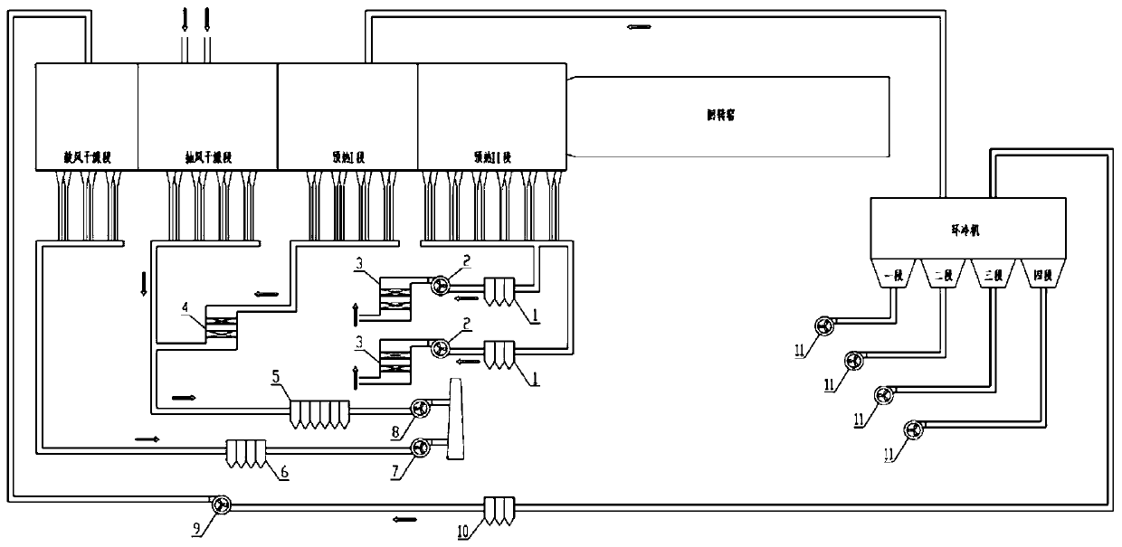
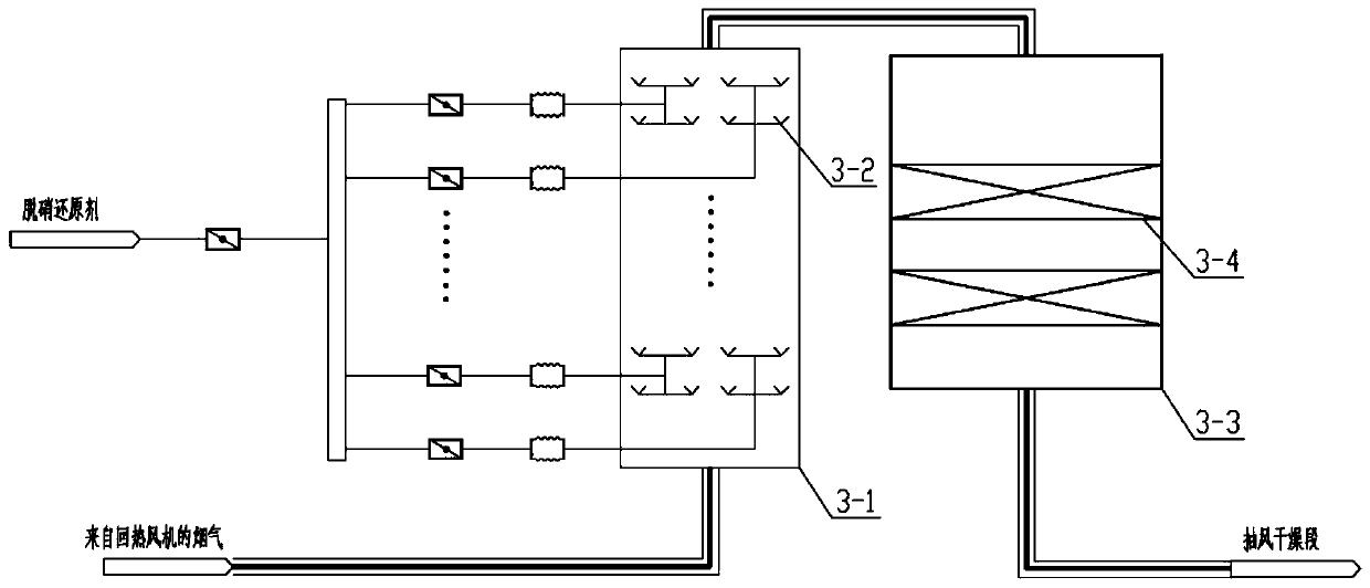
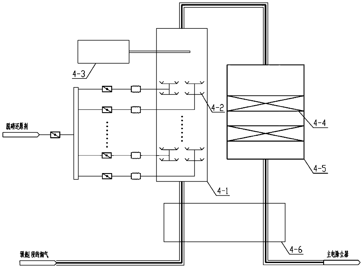
[0024] The denitrification system used in the grate machine-rotary kiln pelletizing equipment of the present invention starts from the principle of nitrogen oxide generation, and sets the SCR denitrification system in combination with the area where nitrogen oxide is generated. Among them, the grate machine-rotary kiln pelletizing equipment is an existing equipment, which includes a chain grate machine, a rotary kiln and an annular cooler connected in sequence, and a part of the exhaust gas of the ann...


PUM


Abstract

The invention discloses a denitration system for grate-rotary kiln pelletizing equipment. The grate-rotary kiln pelletizing equipment comprises a grate, a rotary kiln and an annular cooler which are sequentially connected, wherein the denitration system comprises a first SCR denitration unit arranged at a flue gas outlet of a grate preheating section II and a second SCR denitration unit arranged at a flue gas outlet of a grate preheating section I, wherein the second SCR denitration unit further comprises a flue gas heating subunit. According to the invention, the first SCR denitration unit isarranged at the outlet of the preheating section II, so that flue gas temperature is high, flue gas does not need to be heated, the catalyst activity is good, the investment operation cost is low, the system is simple and high in reliability, the catalyst consumption can be reduced, and the ultra-low emission standard can be met; by arranging the second SCR denitration unit and a flue gas heatingdevice at the flue gas outlet of the preheating section I, the total fuel gas consumption and the investment cost are reduced.

Description

technical field [0001] The invention relates to the technical field of flue gas denitrification, and more specifically, relates to a denitrification system for grate-rotary kiln pellet equipment. Background technique [0002] Pellet ore is the main iron-containing charge for blast furnace ironmaking. Compared with sinter, the production process of pellet ore has low energy consumption and relatively friendly environment, and the product has the advantages of good strength, high grade and good metallurgical performance. It is applied to blast furnace During smelting, it can increase production and save coke, improve ironmaking technical and economic indicators, reduce pig iron cost, and improve economic benefits. Most of the pellet production is based on the chain grate-rotary kiln process. [0003] In recent years, with the increasing complexity of iron ore raw materials and fuels, the increase in the proportion of hematite (leading to an increase in roasting temperature), t...

Claims


Application Information

Patent Timeline
Patent Type & Authority Applications(China)
IPC IPC(8): B01D53/86B01D53/56
CPCB01D53/8625B01D2258/0283
Inventor 杜文韬李灵均杨志忠李元付平田曼曼
Owner DONGFANG BOILER GROUP OF DONGFANG ELECTRIC CORP
Learn More