Optical fiber fourier transform white light interference relative measurement method

A Fourier transform and inverse Fourier transform technology, applied in the field of fiber Fourier transform white light interferometry, can solve the problems of low measurement accuracy and unavoidable fiber transmission.

Active Publication Date: 2008-04-30
BEIJING INSTITUTE OF TECHNOLOGYGY
View PDF0 Cites 7 Cited by
  • Summary
  • Abstract
  • Description
  • Claims
  • Application Information

AI Technical Summary

Problems solved by technology

The wavelength tracking method measures the cavity length by detecting the fringe peak wavelength of the FPI output white light spectrum, which has high sensitivity, but is only applicable to the case of a small cavity length
When the cavity length is small, the linear or quadrature demodulation method also has high sensitivity, but it cannot avoid the influence caused by the change of light s

Method used


Image

  • Optical fiber fourier transform white light interference relative measurement method
  • Optical fiber fourier transform white light interference relative measurement method
  • Optical fiber fourier transform white light interference relative measurement method

Examples


Embodiment 1

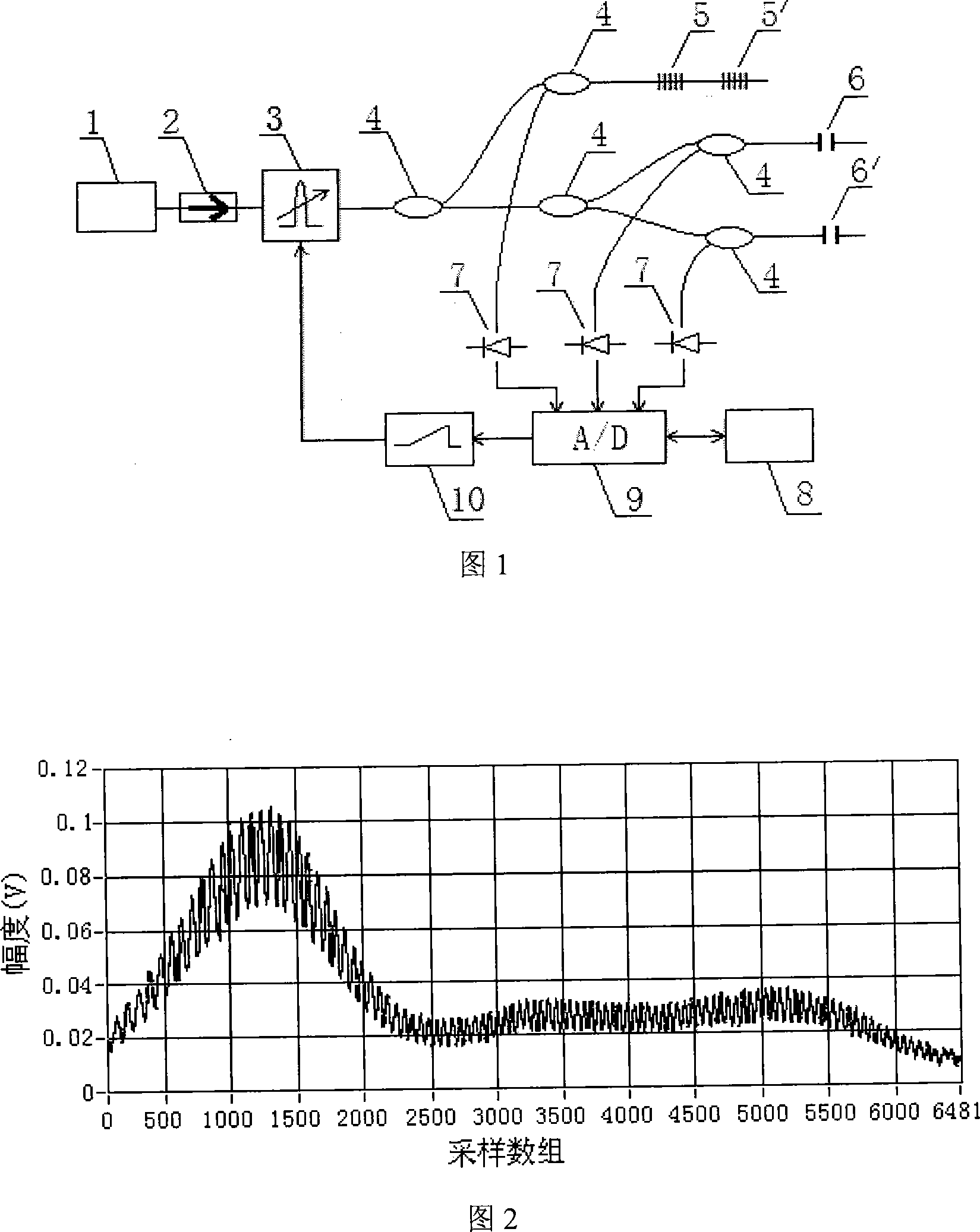
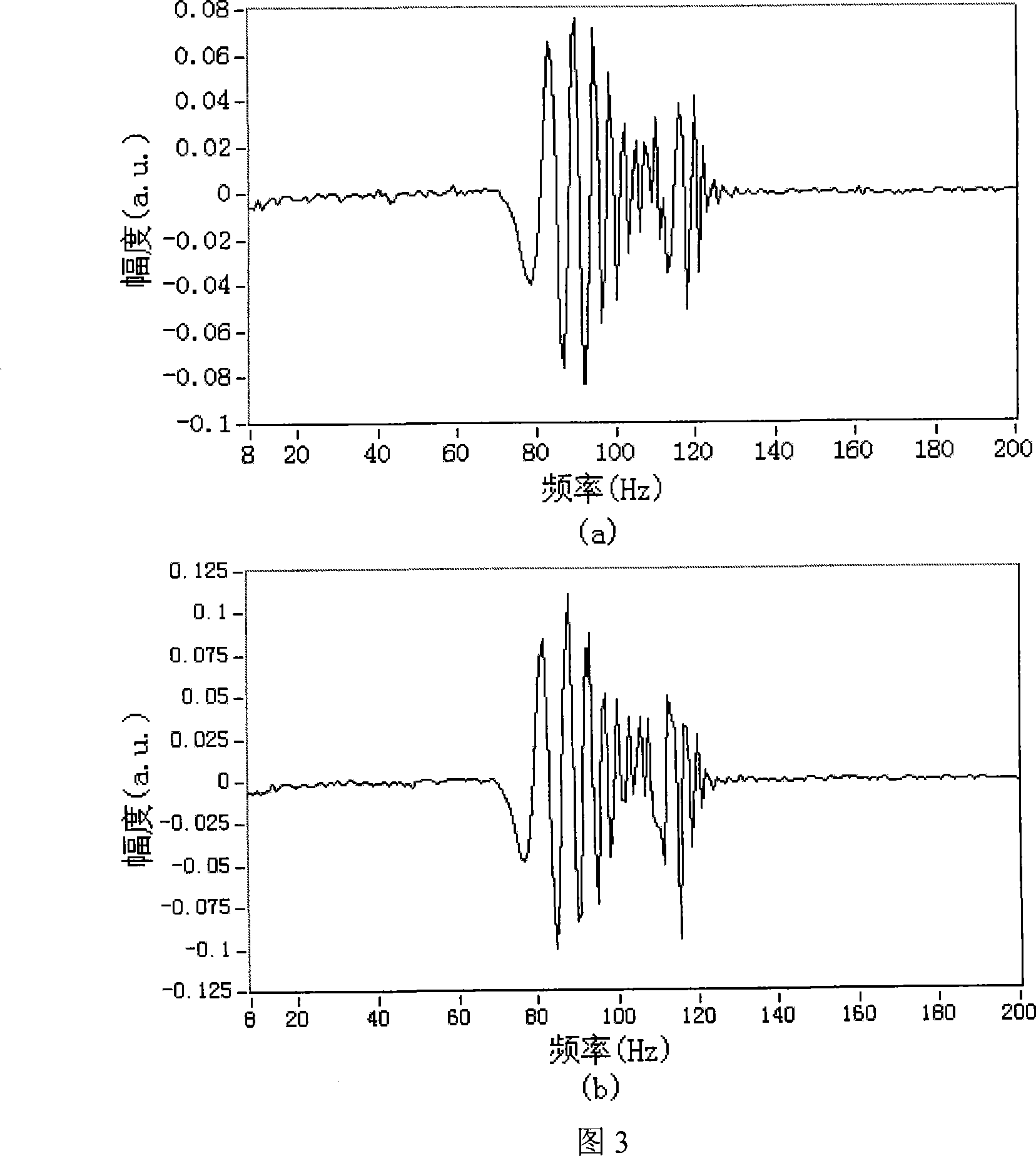
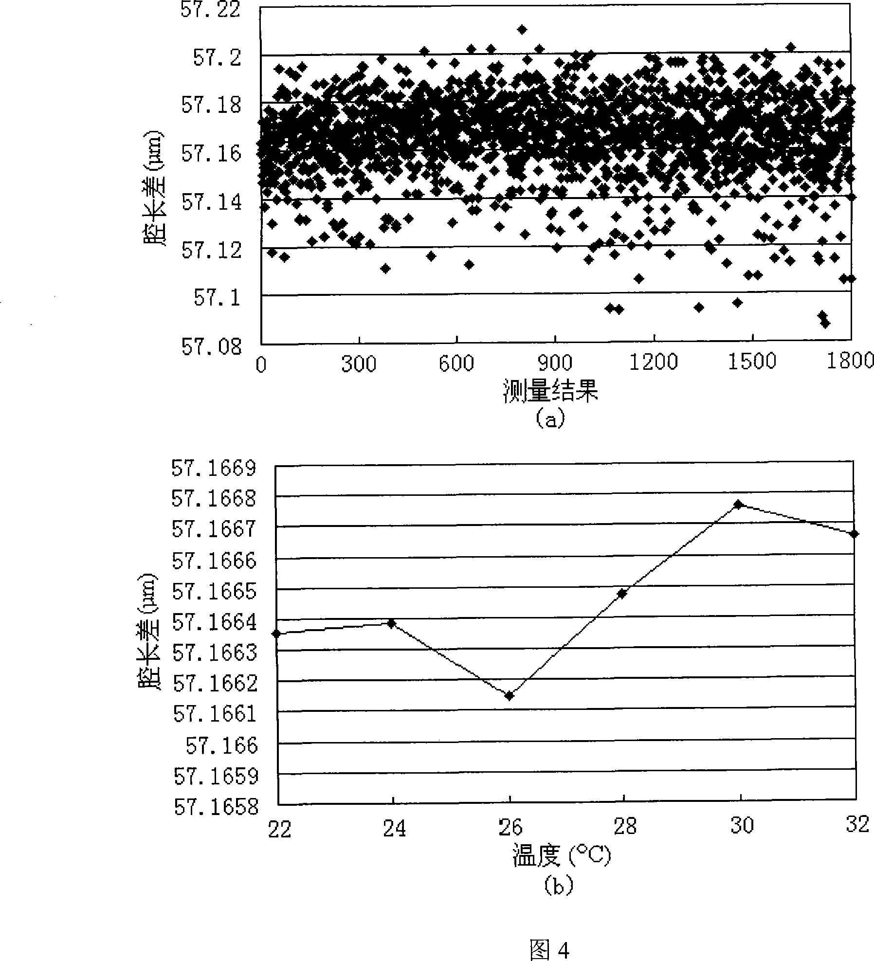
[0043] Fig. 1 is an embodiment figure of the inventive method, and the cavity length measurement of the EFPI fiber optic sensor is used to illustrate the inventive method; the measuring method of the present invention has been verified by experiment, referring to Fig. 2~5.

[0044]The light emitted by the broadband light source 1 is input to the tunable fiber-optic filter 3 through the optical isolator 2, and the tunable fiber-optic filter 3 is driven by the sawtooth wave generator 10 to output the wavelength-scanning narrow-band light, and the wavelength-scanning narrow-band light is A fiber coupler 4 is divided into two paths. One of the wavelength-scanned narrow-band light passes through a fiber coupler 4 and connects two fiber gratings 5, 5' with different center wavelengths, and the starting and stopping wavelengths λ of the measurement are determined by detecting the reflected light of the fiber gratings 5, 5' 1 and lambda 2 . The other wavelength-scanned narrowband li...

Embodiment 2

[0049] Fig. 6 is another embodiment diagram of the method of the present invention. The light emitted by the broadband light source 1 is input to the tunable fiber F-P filter 3 through the optical isolator 2, and the tunable fiber F-P filter 3 is driven by the sawtooth wave generator 10 to output the wavelength-scanning narrow-band light, and the wavelength-scanning narrow-band light is A fiber coupler 4 is divided into two paths, one path of light passes through the etalon 11 and fiber grating 5; the other path of light is input to #1EFPI fiber sensor 6 through the fiber optic coupler 4. The two photodetectors 7 respectively detect the transmitted light of the etalon 11, the fiber grating 5, and the reflected light of the #1EFPI fiber sensor 6. The two detection signals are converted into digital signals by the A / D acquisition card 9 and input to the computer 8 , and the A / D acquisition card 9 simultaneously receives instructions from the computer 8 and outputs control signal...


PUM


Abstract

The invention is an optical fiber Fourier transform white light interference relative measurement method, relates to optical fiber sensor technology, and belongs to the field of optoelectronics. In this method, two Fabry-Perot interferometric (FPI) sensors are selected, one of which is used for sensing and the other is used as a reference; the output white light spectrum of FPI is respectively detected and Fourier transformed, and the Fourier spectrum is carried by the frequency determined by the length of the FPI cavity. Frequency, separated into two groups of symmetrical carrier frequency components in the frequency space; one group of components is filtered out for inverse Fourier transform, the two groups of results are conjugated and multiplied to take the complex logarithm, and the phase difference information of the two FPIs is used as the signal The imaginary part of is separated from the background formed by the spectral profile of the light source and the contrast of the interference fringes, enabling the measurement. Compared with the white light spectrum peak measurement method and the Fourier transform peak frequency measurement method, the measurement accuracy of the method of the invention is greatly improved.

Description

technical field [0001] The invention relates to the technical field of optical fiber sensing, in particular to an optical fiber Fourier transform white light interferometry method. Background technique [0002] The external cavity Fabry-Perot interferometric (EFPI) optical fiber sensor has the advantages of high measurement sensitivity, compact structure, anti-polarization, etc., and has been widely used. To be measured, such as strain, temperature, displacement or pressure, etc., act on the EFPI fiber optic sensor, causing the change of the sensor cavity length, and the cavity length is demodulated from the output interference signal of the sensor, so as to realize the measurement to be measured. Generally, people do not care about the absolute cavity length of the EFPI fiber sensor, but are interested in the variation of the cavity length. For example, if an EFPI fiber optic strain sensor is installed on a certain structure, its initial strain is zero. When the sensor is ...

Claims


Application Information

Patent Timeline
IPC IPC(8): G01J3/28G01J3/45G01J3/26G01J9/02G01D5/353
Inventor 江毅唐才杰
Owner BEIJING INSTITUTE OF TECHNOLOGYGY
Why Eureka
Try Eureka