
6nm-100nm wave band extreme ultraviolet imaging optical instrument imaging quality test device

A 6nm-100nm, extreme ultraviolet imaging technology, which is applied in the field of imaging quality testing devices for extreme ultraviolet imaging optical instruments, can solve the problems that the detection of imaging quality resolution cannot be realized, and the imaging quality detection of extreme ultraviolet imaging systems cannot be realized. Simple, reliable effects

Inactive Publication Date: 2008-04-30
CHANGCHUN INST OF OPTICS FINE MECHANICS & PHYSICS CHINESE ACAD OF SCI
View PDF0 Cites 7 Cited by
  • Summary
  • Abstract
  • Description
  • Claims
  • Application Information

AI Technical Summary

Problems solved by technology

The detection of the imaging quality, especially the resolution, of the extreme ultraviolet imaging optical system cannot be realized by the usual methods mentioned above.
This is because: extreme ultraviolet light cannot propagate in any medium other than vacuum, and conventional resolution plates are obtained by writing on quartz glass or other optical materials, so it cannot be achieved with conventional resolution plates. Imaging Quality Inspection of Extreme Ultraviolet Imaging System

Method used


Image

  • 6nm-100nm wave band extreme ultraviolet imaging optical instrument imaging quality test device
  • 6nm-100nm wave band extreme ultraviolet imaging optical instrument imaging quality test device
  • 6nm-100nm wave band extreme ultraviolet imaging optical instrument imaging quality test device

Examples


specific Embodiment approach 1

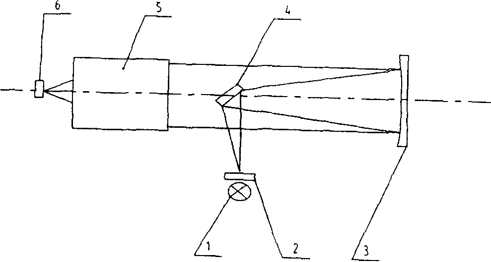
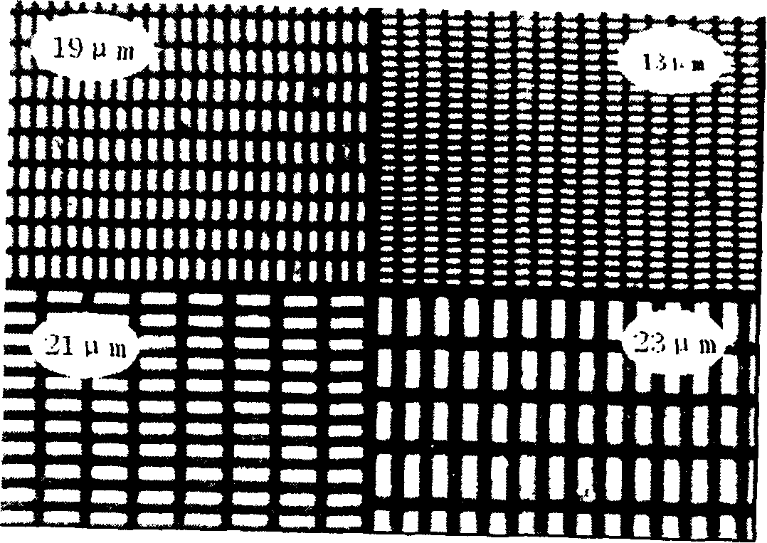
[0012] The entire optical system is under vacuum conditions. The EUV light source 1 emits an EUV light beam that passes through a precision-drawn metal grid 7, hits the mirrors 3 and 4, and finally passes through the EUV imaging optical system 5 to be tested in the EUV camera 6. On the imaging, the grid scale of the metal grid is compared with the formed image, and the resolution data of the optical system to be tested can be obtained after calculation.

[0013] Hollow cathode light source can be selected as the extreme ultraviolet light source, and the grid can be obtained by micro-machining method, and the grid grid precision is 19 μm. Made of nickel metal.

specific Embodiment approach 2

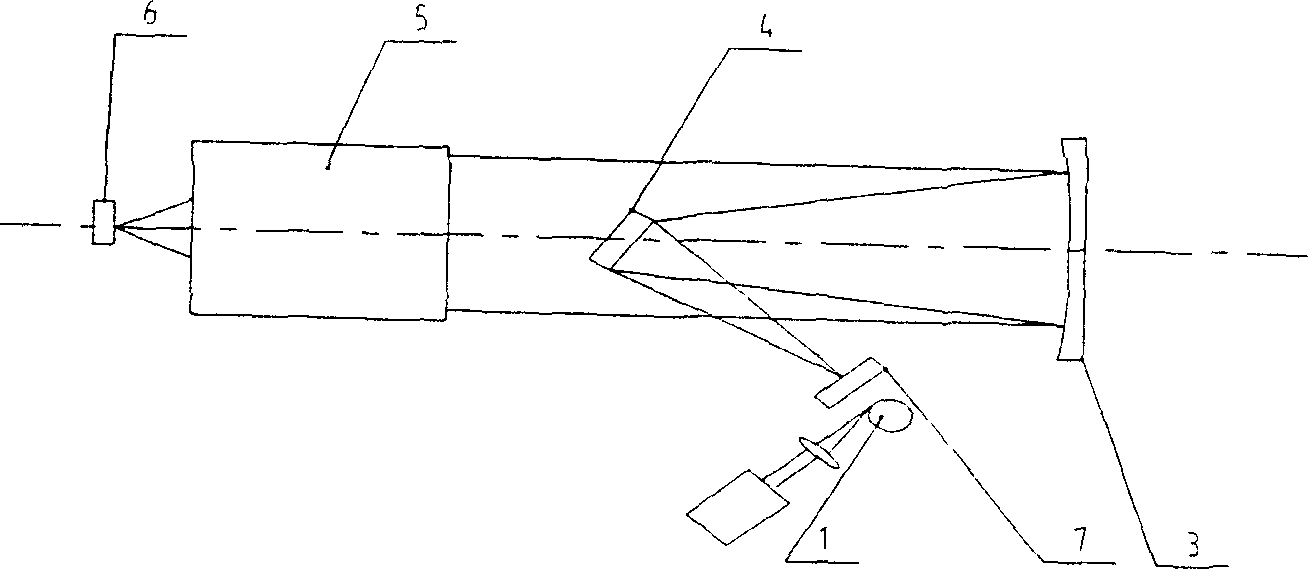
[0014] The entire optical system is under vacuum conditions. The EUV light source 1 emits an EUV light beam that passes through a precision-drawn metal grid 7, hits the mirrors 3 and 4, and finally passes through the EUV imaging optical system 5 to be tested in the EUV camera 6. On the imaging, the grid scale of the metal grid is compared with the formed image, and the resolution data of the optical system to be tested can be obtained after calculation.

[0015] The extreme ultraviolet light source is a laser plasma light source, and the grid can be obtained by the synchrotron radiation LIGA process, and the grid grid accuracy is 13 μm. Made of nickel metal.

specific Embodiment approach 3

[0016] The entire optical system is under vacuum conditions. The EUV light source 1 emits an EUV light beam that passes through a precision-drawn metal grid 7, hits the mirrors 3 and 4, and finally passes through the EUV imaging optical system 5 to be tested in the EUV camera 6. On the imaging, the grid scale of the metal grid is compared with the formed image, and the resolution data of the optical system to be tested can be obtained after calculation.

[0017] The extreme ultraviolet light source is a laser plasma light source, and the grid is obtained by the synchrotron radiation LIGA process, and the grid accuracy is 2 μm. Made of nickel metal.


PUM


Abstract

The invention belongs to the image optical filed of a shortwave segment, in particular to an image quality measuring device for an EUV image optical instrument. The invention includes a measuring device designed referring to the following drawing. The whole optical system is positioned under a vacuum condition. The EUV beam from an EUV light source 1 is bit onto reflectors 3 and 4 after passing through a metal mesh 7 which is carved accurately, and then is imaged on an EUV camera 6 after passing through a measured EUV image optical system 5. The grid size of the metal mesh is compared with the finished image, and the resolution data of the measured optical system is obtained through computation. The invention has the beneficial effects of providing an image quality measuring device for EUV image optical instrument with simple structure and reliable performance.

Description

technical field [0001] The invention belongs to the field of short-wavelength imaging optics, in particular to an imaging quality testing device for extreme ultraviolet imaging optical instruments. Background technique [0002] The imaging quality evaluation of the imaging optical instrument system is an essential link in the development of optical instruments, and it is also one of the important indicators for the functional verification of instrument applications. The evaluation methods of optical system imaging quality mainly include star point method, knife edge method, shadow method, resolution measurement, modulation transfer function measurement and so on. Among them, resolution measurement is the simplest and most direct method. In general, most visible or infrared optical instrument systems use detection methods and devices for resolution measurement such as reference figure 1 , expressed as follows: the parallel light generated by the light source 1 passes throug...

Claims


Application Information

Patent Timeline
IPC IPC(8): G01M11/00G01M11/02
Inventor 巩岩
Owner CHANGCHUN INST OF OPTICS FINE MECHANICS & PHYSICS CHINESE ACAD OF SCI
Features
  • Generate Ideas
  • Intellectual Property
  • Life Sciences
  • Materials
  • Tech Scout
  • Unparalleled Data Quality
  • Higher Quality Content
  • 60% Fewer Hallucinations
Learn More