Supercharge Your Innovation With Domain-Expert AI Agents!

Ion implanter

An ion implanter and ion beam technology, which is applied in the manufacture of discharge tubes, electrical components, semiconductors/solid-state devices, etc., can solve problems such as the inability to ensure the uniformity of ion beam current density distribution, and achieve easy ion implantation and improved uniformity Effect

Inactive Publication Date: 2010-06-23
NISSIN ION EQUIP CO LTD
View PDF5 Cites 0 Cited by
  • Summary
  • Abstract
  • Description
  • Claims
  • Application Information

AI Technical Summary

Problems solved by technology

Therefore, it cannot be guaranteed that the uniformity of the ion beam current density distribution at the implantation position is excellent

Method used


Image

  • Ion implanter
  • Ion implanter
  • Ion implanter

Examples


Embodiment Construction

[0119] (1) Regarding the entire ion implanter

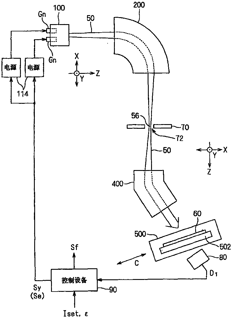
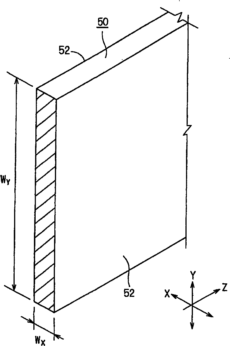
[0120] figure 1 It is a schematic plan view showing an embodiment of the ion implanter of the present invention. In the specification and drawings, the transmission direction of the ion beam 50 is always set as the Z direction, and two directions substantially perpendicular to each other on a plane substantially perpendicular to the Z direction are set as the X and Y directions, respectively. For example, X and Z directions are horizontal directions, and Y direction is vertical directions. The Y direction is a constant direction, while the X direction is not an absolute direction, but varies according to the position of the ion beam 50 on the path (see e.g. figure 1 ). In the specification, the case where the ions constituting the ion beam 50 are positive ions is described as an example.

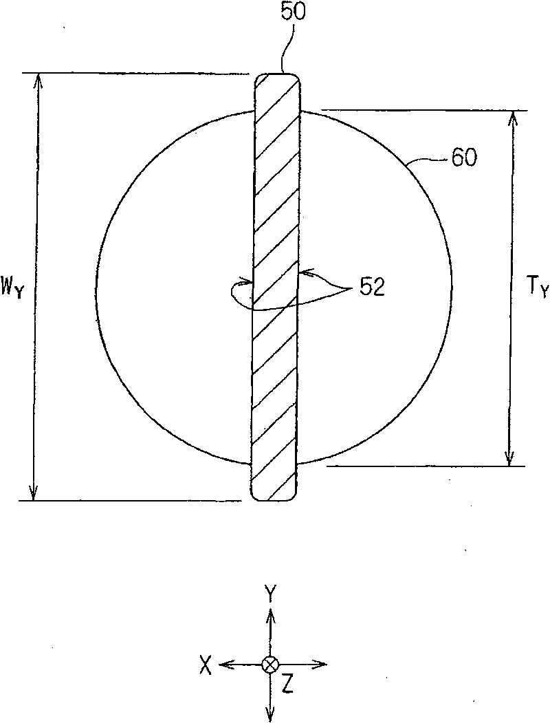
[0121] The ion implanter is an instrument that irradiates a substrate 60 with a ribbon ion beam 50 to perform ion implantation, and includ...


PUM


Abstract

An ion implanting apparatus has: an ion source which generates an ion beam; an electron beam sources which emit an electron beam to be scanned in the Y direction in the ion source; a power source for the sources; an ion beam monitor which, in the vicinity of an implanting position, measures a Y-direction ion beam current density distribution of the ion beam; and a controlling device. The controlling device has a function of homogenizing the Y-direction ion beam current density distribution measured by the monitor, while controlling the power sources on the basis of measurement data of the monitor, by increasing a scanning speed of the electron beam in a position corresponding to a monitor point where an ion beam current density measured by the monitor is large and decreasing the scanning speed of the electron beam in a position corresponding to a monitor point where the measured ion beam current density is small.

Description

technical field [0001] The present invention relates to an ion implanter in which ion implantation is performed on a substrate by using in combination the incidence of a ribbon ion beam on the substrate and the movement of the substrate in a direction intersecting a major surface of the ion beam. Background technique [0002] In this ion implanter, in order to improve the uniformity of ion implantation on the substrate, the longitudinal direction (in the description, Y direction) of the ribbon-shaped (also called sheet-shaped or strip-shaped, the same below) ion beam is increased. Homogenization of ion beam current density distribution is important. [0003] As a technique for improving the uniformity of the ion beam current density distribution in the longitudinal direction of the ribbon ion beam, for example, Patent Document 1 discloses a technique in which the filament current of an ion source having a plurality of filaments is controlled to The uniformization of the ion...

Claims


Application Information

Patent Timeline
Patent Type & Authority Patents(China)
IPC IPC(8): H01J37/317H01L21/265
CPCH01J37/09H01J37/241H01J37/252H01J37/30H01J37/3171H01J37/32935H01L21/26586
Inventor 山下贵敏藤田秀树
Owner NISSIN ION EQUIP CO LTD
Features
  • R&D
  • Intellectual Property
  • Life Sciences
  • Materials
  • Tech Scout
  • Unparalleled Data Quality
  • Higher Quality Content
  • 60% Fewer Hallucinations
Learn More