Heat exchanger

A heat exchanger and core tube technology, which is applied in heat exchange equipment, indirect heat exchangers, heat exchanger types, etc., can solve the problem of poor contact between the core tube and the coil tube, the strength of the raised part is reduced, and the heat transfer performance is reduced. and other problems to achieve the effect of eliminating poor contact, avoiding strength reduction, and improving heat transfer performance

Inactive Publication Date: 2008-05-07
DAIKIN IND LTD
View PDF1 Cites 3 Cited by
  • Summary
  • Abstract
  • Description
  • Claims
  • Application Information

AI Technical Summary

Problems solved by technology

[0005] However, when using a core tube in which protrusions are provided on the inner surface of the core tube of the heat exchanger by pressing the outer surface, the outer surface of the core tube corresponding to the portion where the protrusion is formed on the inner surface form a depression
When the coiled tube is wound on the core tube in this state, and then wound into an oblong spiral shape, since the cross section of

Method used


Image

  • Heat exchanger
  • Heat exchanger
  • Heat exchanger

Examples


Embodiment 1

[0035] The heat exchanger of the present invention is explained with reference to the drawings and examples.

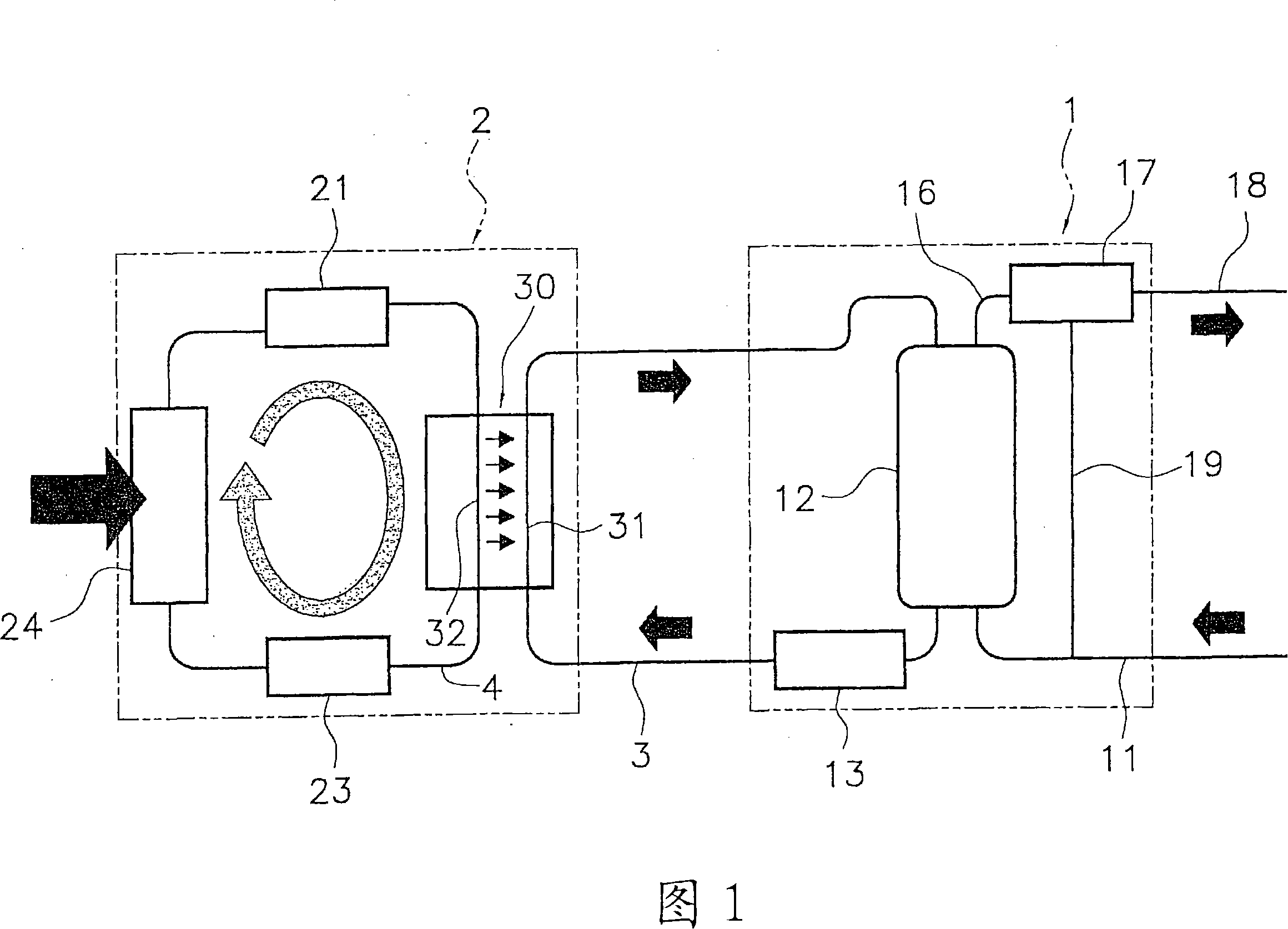
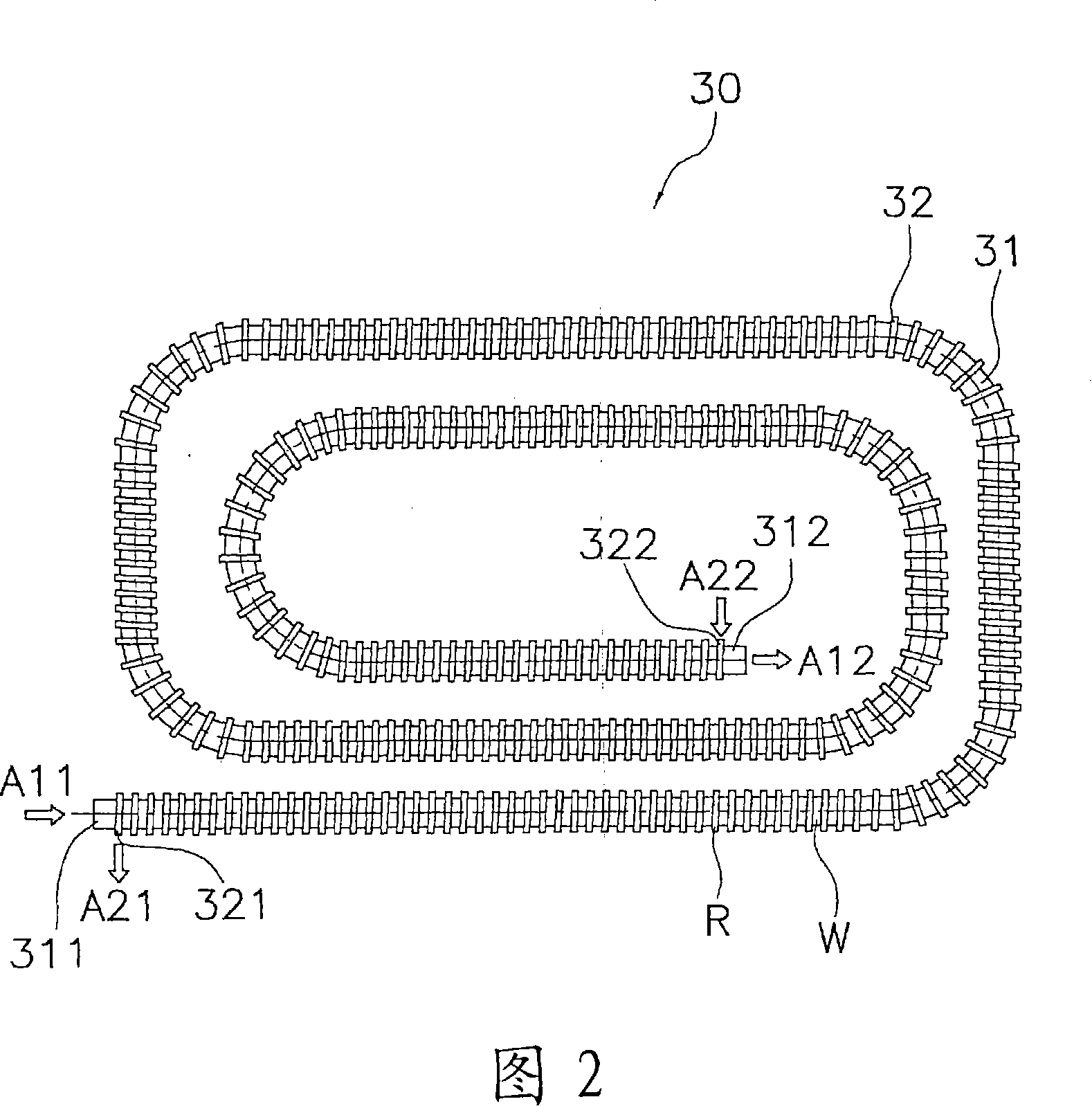
[0036] Fig. 1 is a schematic diagram of a heat pump water heater using the heat exchanger of the present invention. In the heat pump type water heater shown in FIG. 1, it takes a long time to heat water from about 10 degrees to about 90 degrees in one direction in order to efficiently use nighttime electricity which is cheap in electricity costs. Here, the heat pump water heater has a water supply unit 1 and a heat pump unit 2 . The hot water supply unit 1 is connected in sequence with a tap water pipe 11, a hot water storage tank 12, a water circulation pump 13, a water supply pipe 3, a core pipe 31 constituting a water heat exchanger 30, a warm water pipe 16, a mixing valve 17 and a heat supply unit. water pipe18. Here, tap water is supplied from the tap water pipe 11 to the hot water storage tank 12 . Water at a low temperature is supplied from the bottom of the...

Embodiment 2

[0043] As shown in FIG. 6 , in Example 2, for a heat exchanger in which a plurality of coil tubes 42 , 42 are spirally wound on a core tube 41 , paste solder 43 accommodated in a container 45 is coated. After applying to the coiled pipes 42, 42, brazing is performed using a heating furnace not shown. At this time, the solder 43 melted by heating is poured into the concave portion 414 by capillary suction. Therefore, in the heat exchanger in which a plurality of coil tubes 42 , 42 are helically wound around the core tube 41 , the working efficiency of brazing can be improved. Furthermore, the solder melted by heating is reliably poured into the concave portion, and the cooling adhesion occurs. Therefore, the recess formed on the outer surface of the core pipe is reliably filled with the brazing filler metal, so that poor contact between the core pipe and the coil pipe can be eliminated. And, in the processing of the protrusions, even if the wall thickness of the protrusions o...

Embodiment 3

[0045] As shown in FIG. 7 , in Embodiment 3, the heat transfer tubes 42 forming the refrigerant passage R are not coiled tubes but straight tubes. That is, in the heat exchanger 50, the straight pipe 42 forming the refrigerant passage R is arranged on the outer surface of the core pipe 51 forming the water passage W. Here, the paste-like brazing material 53 is applied in advance to the concave portion 514 formed on the outer surface of the core tube 51 , and then the straight tube 52 is placed on the core tube 51 and brazed using a heating furnace not shown. Then, the solder 53 melted by heating is reliably poured into the concave portion 514, and the cooling sticking occurs. Therefore, the concave portion 514 formed on the outer surface of the core tube 51 is reliably filled with the solder 53 , so that poor contact between the core tube 51 and the straight tube 52 can be eliminated. And, in the process of protruding, even if the wall thickness of the protruding portion 513 ...


PUM


Abstract

A brazing material 315 in a paste form is applied in advance to dented portions 314 formed on the outer surface of a core pipe 31, and then a pipe 32 is disposed on the pipe 31, and brazing is carried out in a furnace. In this way, the brazing material 315 that was melted by the heat will be reliably poured into the dented portions 314 and bonded thereto after being cooled down. Thus, the dented portions 314 formed on the outer surface of the core pipe 31 can be reliably filled with the brazing material 33, which consequently eliminates a poor contact between the core pipe 31 and the winding pipe 32. In addition, even if the wall thickness of portions in which projections 313 are formed are made thinner in the process of forming the projections, the dented portions 314 formed on the outer surface are filled with the brazing material 33, so that the core pipe thickness can be reinforced, and the reduction in strength of the portions with the projections 313 can be prevented.

Description

technical field [0001] The present invention relates to a heat exchanger, and more particularly to a heat exchanger having a core tube formed with protrusions on the inner surface by pressing the outer surface and a coil tube wound on the outer surface of the core tube. Background technique [0002] Among the heat exchange devices used in air conditioners, water heaters, etc., some are provided with a heat exchanger having a core tube forming a flow path for the first fluid and a core tube wound on the outer surface of the core tube and forming a second fluid flow path. A coil of flow passages, the heat exchanger performs heat exchange between the first fluid and the second fluid. For example, as a heat exchanger for hot water supply such as a heat pump water heater, there is a double-tube heat exchanger disclosed in Patent Document 1, which consists of a core tube through which water flows and a disc through which refrigerant flows. The tube consists of a double tube, and ...

Claims


Application Information

Patent Timeline
IPC IPC(8): F28D7/02
CPCF28F1/426B23K1/0012B23K2201/001F28D7/024F28D7/022F28D7/0016F28F1/06F28F1/02B23K2101/001F28D7/02
Inventor 沼田光春柴田豊
Owner DAIKIN IND LTD
Why Eureka
Try Eureka