Resin composition
A resin composition and resin technology, applied in the field of resin composition, can solve problems such as low transparency, low compatibility of blended resins, complicated process, etc., and achieve easy control, excellent transparency and heat resistance, and easy manufacture Effect
- Summary
- Abstract
- Description
- Claims
- Application Information
AI Technical Summary
Problems solved by technology
Method used
Image
Examples
Embodiment
[0102] The present invention will be described in detail based on examples, but the present invention is not limited to these examples. In addition, the respective measurement methods of the physical properties measured in the following Examples and Comparative Examples are as follows.
[0103] (1) Determination of imidization rate
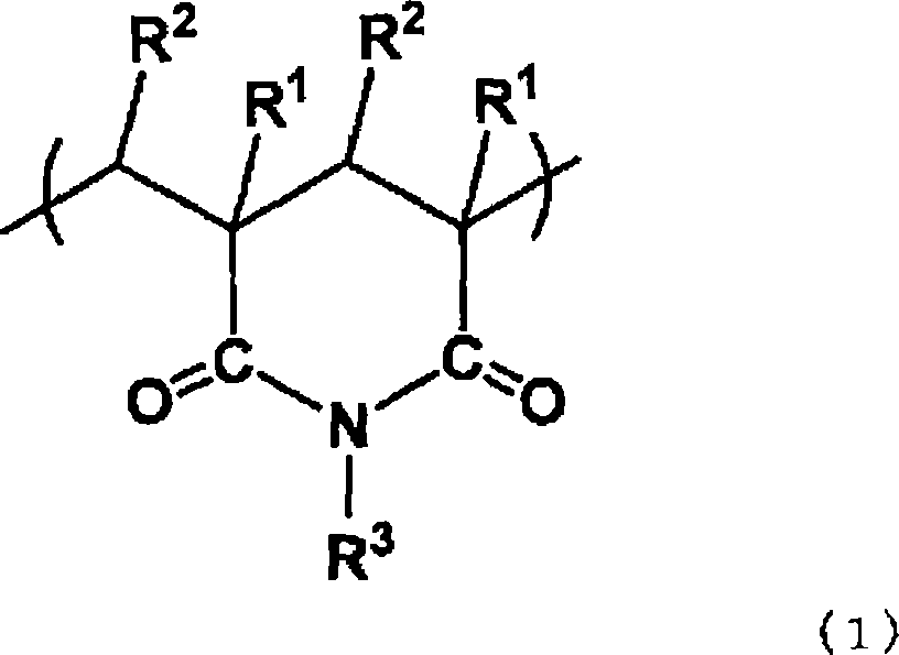
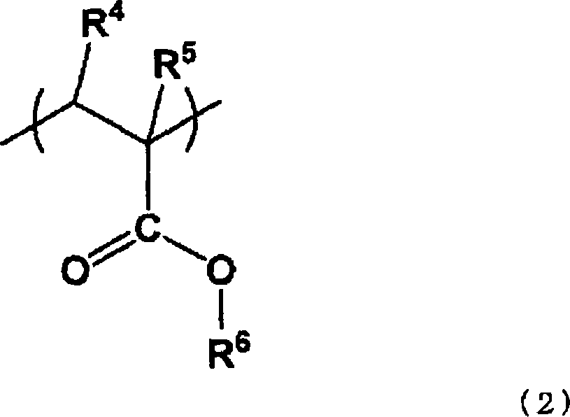
[0104] The product pellets were used as they were, and the IR spectrum was measured at room temperature using TravelIR manufactured by SensIR Technologies. According to the spectrum obtained, from 1720cm -1 The absorption intensity attributable to the ester carbonyl and the 1660cm -1 The ratio of the absorption intensity assigned to the imide carbonyl group was used to obtain the imidization rate. Here, the imidation ratio means the ratio of imide carbonyl groups to all carbonyl groups.
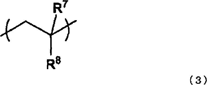
[0105] (2) Styrene content
[0106] Dissolve 10 mg of the product in CDCl 3 1 g, measured at room temperature using an NMR measuring device Gemini-300 man...
manufacture example 1
[0116] An imide resin was produced using a commercially available methacrylic resin (Sumitomo Chemical Industries, Ltd., SumipexMH) and monomethylamine as an imidation agent. The extruder used was a bite-type co-rotating twin-screw extruder with a diameter of 40 mm. The methacrylic resin was supplied at 20 kg / hr under the conditions of a set temperature of 270° C. and a screw rotation speed of 200 rpm in each temperature control zone of the extruder, and the supply amount of monomethylamine was 25 wt. per methacrylic resin. share. A methacrylic resin was charged from a hopper, and after the resin was melted and filled with a kneading block, monomethylamine was injected from a nozzle. Install a gasket at the end of the reaction zone to keep the resin filled. The vent pressure was reduced to -0.09MPa to volatilize the by-products and excess methylamine after the reaction. The resin extruded in filament form from a die installed at the exit of the extruder was cooled in a wate...
manufacture example 2
[0121] In the same manner as in Production Example 1, an imide resin was produced using a methyl methacrylate-styrene copolymer (22% by weight of St content) and monomethylamine as an imidating agent. Under the conditions of setting temperature of 270°C in each temperature control area of the extruder and screw rotation speed of 200rpm, polymethyl methacrylate-styrene copolymer was supplied at 20kg / hr, and the supply amount of monomethylamine was relative to that of polymethylamine. 20 parts by weight of methyl acrylate-styrene copolymer.
[0122] Table 1 shows the imidization rate, glass transition temperature, and styrene content of the obtained imide resin (b).
PUM
 Abstract
Description
Claims
Application Information
 - R&D
- Intellectual Property
- Life Sciences
- Materials
- Tech Scout
- Unparalleled Data Quality
- Higher Quality Content
- 60% Fewer Hallucinations
Browse by: Latest US Patents, China's latest patents, Technical Efficacy Thesaurus, Application Domain, Technology Topic, Popular Technical Reports.
© 2025 PatSnap. All rights reserved.Legal|Privacy policy|Modern Slavery Act Transparency Statement|Sitemap|About US| Contact US: help@patsnap.com


