Grate bar and grate for a step-grate stoker

A furnace bar and grate technology, which is applied in the field of furnace bars and grates used for step-by-step grate stokers, can solve the problem of expanding the interval between furnace bars, failing to fully prevent the continuous accumulation of refractory materials, and increasing the difficulty of adjusting combustion and other issues, to achieve the effect of reducing risks, effective and well-distributed combustion

Inactive Publication Date: 2008-05-14
萨锐特克
View PDF0 Cites 2 Cited by
  • Summary
  • Abstract
  • Description
  • Claims
  • Application Information

AI Technical Summary

Problems solved by technology

These bars are particularly limited to the aforementioned bars whose main part is in the shape of an inverted "U" since the path of travel of the particles removed between the bars corresponds to the thickness of the flattened portion, making this path shorter Defects
[0008] However, these bars do not adequately prevent the continuous accumulation of refractory material between and below the bars
This accumulation can then lead

Method used


Image

  • Grate bar and grate for a step-grate stoker
  • Grate bar and grate for a step-grate stoker
  • Grate bar and grate for a step-grate stoker

Examples


Embodiment Construction

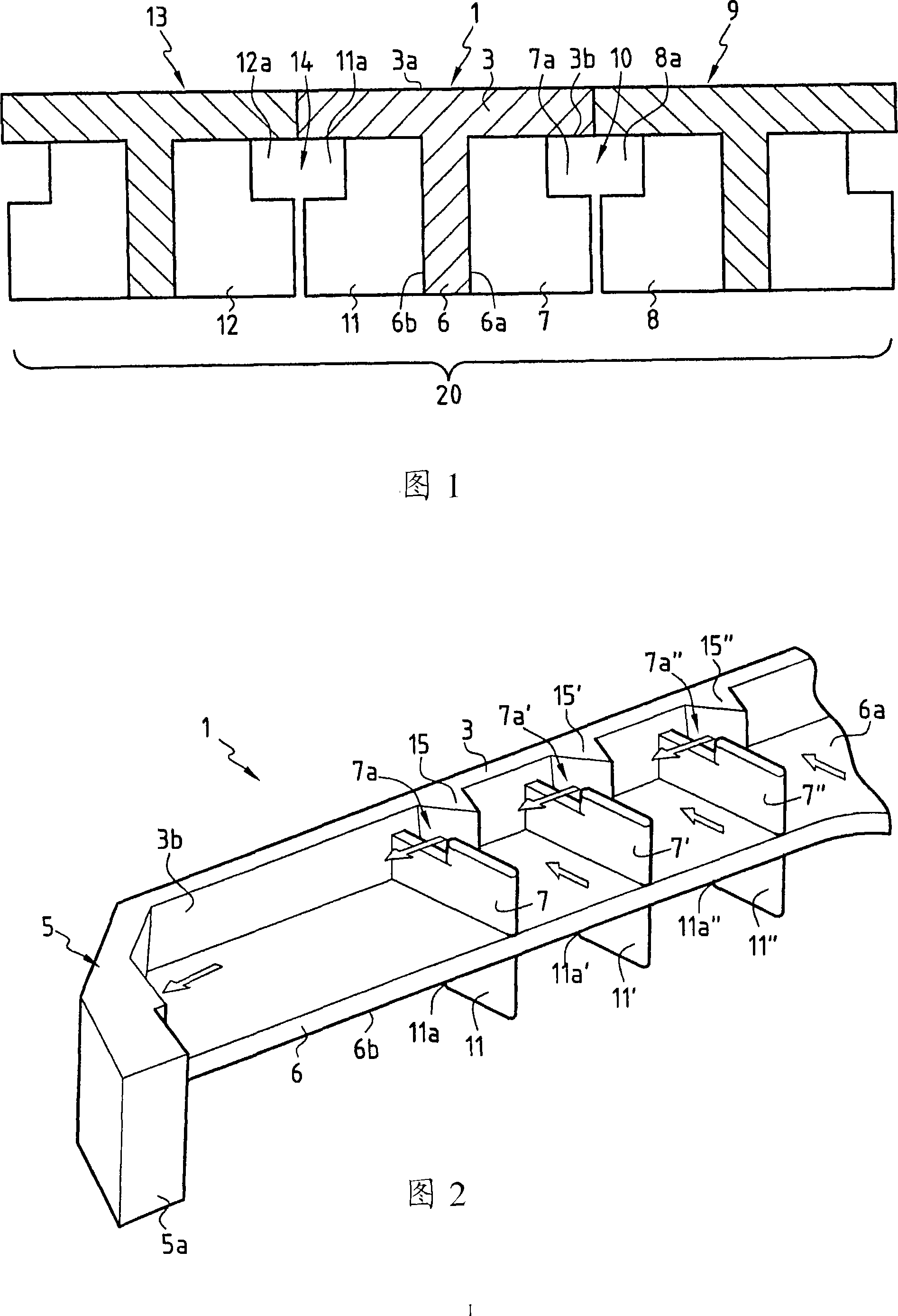
[0045] Figure 1 schematically shows a cross-sectional view of a set of three bars according to the invention.

[0046] In this figure three bars 1 , 9 , 13 are shown. It can be observed that the main part of each bar is "T" shaped, as in the case of bar 1 , with the flat part 3 atop the longitudinal projection 6 . Among other advantages, this "T" shaped main part, due to its moment of inertia, offers a preferred level of geometrical and mechanical precision, as well as a better resistance to deformation at high temperatures.

[0047] The materials used are preferably refractory alloys with high resistance to thermal wear, thermal corrosion, oxidation and thermal shock. Cast manufacturing methods allow the realization of such high fusion and high melting point alloys. The "T" shaped main part, fully removable from its mold, allows the use of a "natural" casting method which has the particular advantage of being considerably easier than other more complex casting methods.

[...


PUM


Abstract

The invention concerns a grate bar and a grate for a step-grate stoker that is used in the field of furnaces for refuse conversion units. The invention thus relates, according to a first aspect, to a grate bar for a stoker of an incinerator, comprising a tray whose upper surface makes it possible to receive the incinerated elements and which extends with a rear end and a front end each forming a return serving as a bearing point for the bar. The bar also comprises a longitudinal projection situated under the tray and extending at least partially between the rear and front ends of the bar. The invention is characterized in that at least one angular cutting element or cutter is placed under the tray, on a first side of the longitudinal projection, having the function of facilitating the evacuation of the progressively accumulated refractory materials. Under the tray and on one side of the longitudinal projection, the grate bar comprises one or more cooling side wing, possibly, arranging with a side cavern allowing gas to ventilate. The grate comprises at least one grate bar or a set of three grate bars. In a second condition, the central grate bar of which is able to move relatively to the two side bars.

Description


Claims


Application Information

Patent Timeline
Owner 萨锐特克
Why Eureka
Try Eureka