Magnetic force pump

A magnetic pump and magnetic drive technology, applied in the field of magnetic pumps, can solve the problems of lack of anti-corrosion friction damping, strength and high temperature resistance, etc., and achieve the effects of widening the scope of use, reducing energy consumption, and excellent corrosion resistance

Inactive Publication Date: 2008-05-28
蔡国华
View PDF0 Cites 4 Cited by
  • Summary
  • Abstract
  • Description
  • Claims
  • Application Information

AI Technical Summary

Problems solved by technology

The magnetic pump in the prior art uses metal to make components with high strength requirements such as the pump casing, impeller, and inner coupling. Although the strength can meet the requirements, it is still lacking in corrosion resistance and frictional damping reduction.
The use of plastic-made spacer sleeves, sliding bearings, thrust bearings and other components reduces their strength and high temperature resistance.

Method used


Image

  • Magnetic force pump
  • Magnetic force pump

Examples


Embodiment 1

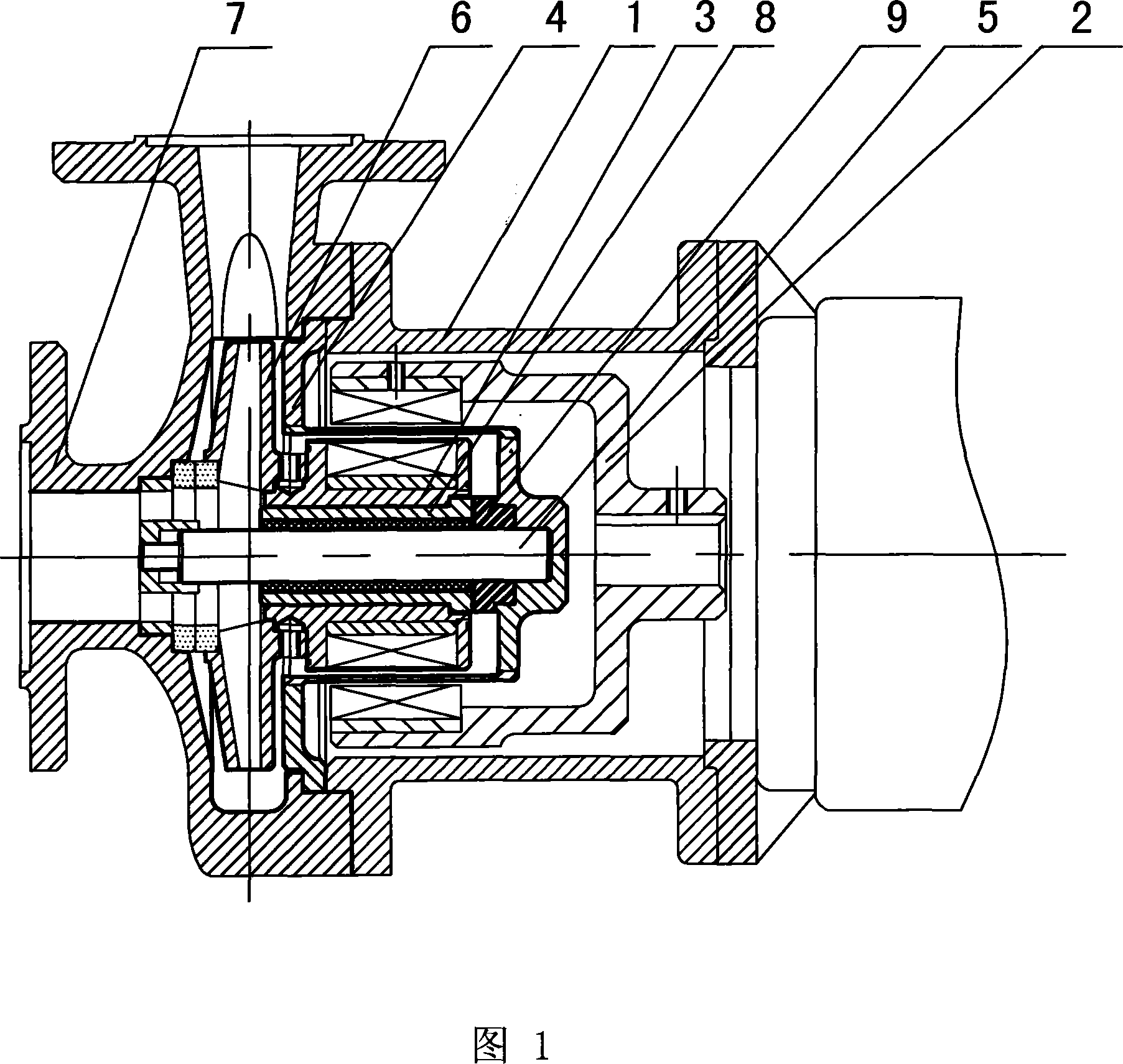
[0019] Embodiment 1 is a direct-coupled magnetic pump. It includes a bracket 1, an outer coupling 2 directly connected to the motor and driven by the motor, an inner coupling 3 concentrically arranged with the outer coupling 2, and an inner coupling 3 arranged between the outer coupling 2 and the inner coupling 3. Spacer sleeve 4 between them, pump shaft 5 connected to inner coupling 3 at one end, impeller 6 installed on pump shaft 5, pump casing 7 located outside of pump shaft 5 and fixedly connected with bracket 1, and A sliding bearing 8 and a thrust bearing 9 are concentrically arranged on the pump shaft 5 . Wherein, the outer coupling 2 drives the inner coupling 3 to rotate through magnetic force, and then drives the impeller 6 to rotate.

[0020] The inner surface of the pump casing 7, the entire surface of the impeller 6, the entire surface of the inner coupling 3, the entire surface of the pump shaft 5, the entire surface of the spacer 4, the entire surface of the sli...

Embodiment 2

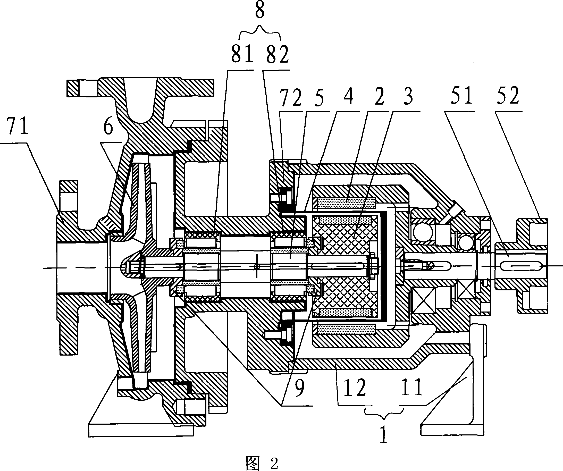
[0023] Embodiment 2 is a suspension type plastic magnetic pump. Its structure differs from that of Embodiment 1 in that: the bracket 1 is composed of a bracket 11 and a suspension 12 fixedly mounted on the bracket 11 . The pump housing 7 includes a pump housing front cover 71 located at the front end of the magnetic pump and a middle body 72 fixedly connected to the rear end of the front cover. The other end of the middle body 72 is fixedly connected to the suspension 12 . The pump shaft 5 is rotatably installed in the chamber surrounded by the middle body 72 . The outer coupling 5 is connected with the motor through a transmission shaft 51 and an extended coupling 52 arranged concentrically with the transmission shaft 51 . The transmission shaft 51 is rotatably arranged on the suspension 12 . The sliding bearing 8 is divided into two sections, a first sliding bearing 81 and a second sliding bearing 82 .

[0024] In this embodiment, the pump casing 7 is made of metal, and i...


PUM

PropertyMeasurementUnit
Thicknessaaaaaaaaaa

Abstract

The invention relates to a magnetic pump, which comprises a support bracket, a motor, an outer coupler which is driven by the motor, an inner coupler which is concentrically provided with the outer coupler and is driven by the magnetic force of the outer coupler to rotate, a separation sleeve which is arranged between the outer coupler and the inner coupler, a pump shaft of which one end is connected with the inner coupler, a blade wheel which is installed on the pump shaft, a pump casing which is located on the outer portion of the outer pump shaft and is fixedly connected with the support bracket, and a sliding bearing and a trust bearing which are concentrically provided with the pump shaft. The surfaces of the pump casing, the blade wheel, the inner coupler, the pump shaft, the separation sleeve, the sliding bearing and the trust bearing are coated with polyetheretherketone resin, or the blade wheel, the separation sleeve, the pump shaft, the sliding bearing, and the trust bearing are made from polyetheretherketone resin, which can greatly increase the use field and the use temperature of the plastic magnetic pump, reduces the friction resistance and energy consumption in working, avoids elements from deforming, and increases the service life.

Description

technical field [0001] The invention relates to a magnetic pump. Background technique [0002] The magnetic pump drives the outer coupling to rotate through the motor, the outer coupling drives the inner coupling to rotate through magnetic force, and the inner coupling drives the impeller to rotate. There is no physical contact and friction between the inner and outer couplings. However, there will still be friction and collision between the inner surface of the pump casing, the surface of the impeller, inner coupling, spacer sleeve, pump shaft, sliding bearing and thrust bearing, and other components. At the same time, when the magnetic pump is working, the temperature and pressure in the pump casing are very high, so there are also high requirements for the heat resistance, hardness and strength of the isolation sleeve, inner and outer couplings and other components. The magnetic pump in the prior art uses metal to make components with high strength requirements such as ...

Claims


Application Information

Patent Timeline
IPC IPC(8): F04D7/06F04D29/02
Inventor 蔡国华
Owner 蔡国华
Why Eureka
Try Eureka